8. In the figure at the left is shown part of the circuit that is used to model the cell membrane of an electrically excitable cell. While the actual model includes variable resistors, let's analyze the simplest example of this circuit: take the batteries to be identical and ideal and the resistors to be identical and Ohmic. The capacitor plates (inside the plastic shell shown) correspond to the inside and outside of the membrane. capacitor R: Duracell resistors batteries Duracell Duracell R: Suppose the batteries each are labeled with a voltage Vo and the resistors each have a resistance R. Where asked for currents or voltages express your answers in terms of V, and R. A. Note that the batteries are not all connected with the same orientation. When the network reaches a steady state is there any current through the batteries and resistors? Explain briefly wh you think so. .B. If you think that there is no current in the batteries and resistors in the steady state, find the voltage drop acr oss each resistor. If you think that there is current, find the current through and voltage drop across each resistor. .C. Is there a voltage difference across the plates of the capacitor? If so, find it. If not, explain why there is none.
8. In the figure at the left is shown part of the circuit that is used to model the cell membrane of an electrically excitable cell. While the actual model includes variable resistors, let's analyze the simplest example of this circuit: take the batteries to be identical and ideal and the resistors to be identical and Ohmic. The capacitor plates (inside the plastic shell shown) correspond to the inside and outside of the membrane. capacitor R: Duracell resistors batteries Duracell Duracell R: Suppose the batteries each are labeled with a voltage Vo and the resistors each have a resistance R. Where asked for currents or voltages express your answers in terms of V, and R. A. Note that the batteries are not all connected with the same orientation. When the network reaches a steady state is there any current through the batteries and resistors? Explain briefly wh you think so. .B. If you think that there is no current in the batteries and resistors in the steady state, find the voltage drop acr oss each resistor. If you think that there is current, find the current through and voltage drop across each resistor. .C. Is there a voltage difference across the plates of the capacitor? If so, find it. If not, explain why there is none.

Introductory Circuit Analysis (13th Edition)
13th Edition
ISBN:9780133923605
Author:Robert L. Boylestad
Publisher:Robert L. Boylestad
Chapter1: Introduction
Section: Chapter Questions
Problem 1P: Visit your local library (at school or home) and describe the extent to which it provides literature...

Related questions
Question

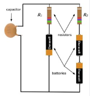
Transcribed Image Text:8. In the figure at the left is shown part of the circuit that is
used to model the cell membrane of an electrically excitable
cell.* While the actual model includes variable resistors, let's
analyze the simplest example of this circuit: take the batteries
to be identical and ideal and the resistors to be identical and
Ohmic. The capacitor plates (inside the plastic shell shown)
correspond to the inside and outside of the membrane.
capacitor
R:
Duracell
resistors
batteries
Duracell
Duracell
R₂
Suppose the batteries each are labeled with a voltage V, and the
resistors each have a resistance R. Where asked for currents or voltages express your answers in
terms of V, and R.
A. Note that the batteries are not all connected with the same orientation. When the network
reaches a steady state is there any current through the batteries and resistors? Explain briefly why
you think so.
.B. If you think that there is no current in the batteries and resistors in the steady state, find the
voltage drop acr
oss each resistor. If you think that there is current, find the current through and voltage drop
across each resistor.
.C. Is there a voltage difference across the plates of the capacitor? If so, find it. If not, explain
why there is none.
Expert Solution
Step 1
The given circuit is shown below.
Both the resistors are identical and .
All the batteries are identical and EMFs of all the three batteries are . The orientation of batteries are not same.

Trending now
This is a popular solution!

Step by step
Solved in 7 steps with 7 images

Knowledge Booster


Learn more about
Need a deep-dive on the concept behind this application? Look no further. Learn more about this topic, electrical-engineering and related others by exploring similar questions and additional content below.Recommended textbooks for you
Introductory Circuit Analysis (13th Edition)
Electrical Engineering
ISBN:
9780133923605
Author:
Robert L. Boylestad
Publisher:
PEARSON

Delmar's Standard Textbook Of Electricity
Electrical Engineering
ISBN:
9781337900348
Author:
Stephen L. Herman
Publisher:
Cengage Learning

Programmable Logic Controllers
Electrical Engineering
ISBN:
9780073373843
Author:
Frank D. Petruzella
Publisher:
McGraw-Hill Education
Introductory Circuit Analysis (13th Edition)
Electrical Engineering
ISBN:
9780133923605
Author:
Robert L. Boylestad
Publisher:
PEARSON
Delmar's Standard Textbook Of Electricity
Electrical Engineering
ISBN:
9781337900348
Author:
Stephen L. Herman
Publisher:
Cengage Learning
Programmable Logic Controllers
Electrical Engineering
ISBN:
9780073373843
Author:
Frank D. Petruzella
Publisher:
McGraw-Hill Education

Fundamentals of Electric Circuits
Electrical Engineering
ISBN:
9780078028229
Author:
Charles K Alexander, Matthew Sadiku
Publisher:
McGraw-Hill Education

Electric Circuits. (11th Edition)
Electrical Engineering
ISBN:
9780134746968
Author:
James W. Nilsson, Susan Riedel
Publisher:
PEARSON

Engineering Electromagnetics
Electrical Engineering
ISBN:
9780078028151
Author:
Hayt, William H. (william Hart), Jr, BUCK, John A.
Publisher:
Mcgraw-hill Education,