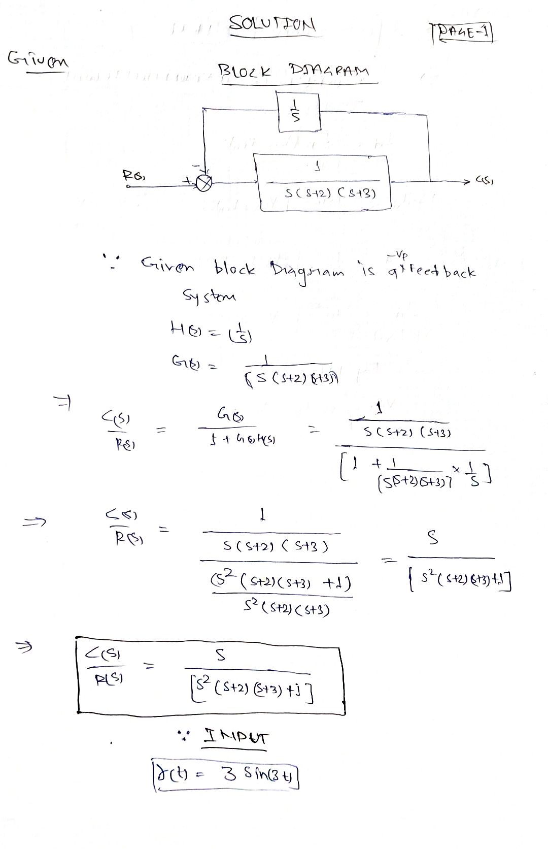
7. Suppose that we have a circuit in a Blackbox, i.e., we don't know the circuit model. After some experimentation, we discover the block diagram of the system (shown below), where r(t) is our input voltage and c(t) is our output voltage. What is the analytical magnitude and frequency response of the system? Now, suppose that the system's time domain input is 3 sin 3t. What is the steady state output Cs(t)? R(s) + 1 S 1 s(s+ 2)(s + 3) C(s)
7. Suppose that we have a circuit in a Blackbox, i.e., we don't know the circuit model. After some experimentation, we discover the block diagram of the system (shown below), where r(t) is our input voltage and c(t) is our output voltage. What is the analytical magnitude and frequency response of the system? Now, suppose that the system's time domain input is 3 sin 3t. What is the steady state output Cs(t)? R(s) + 1 S 1 s(s+ 2)(s + 3) C(s)

Introductory Circuit Analysis (13th Edition)
13th Edition
ISBN:9780133923605
Author:Robert L. Boylestad
Publisher:Robert L. Boylestad
Chapter1: Introduction
Section: Chapter Questions
Problem 1P: Visit your local library (at school or home) and describe the extent to which it provides literature...

Related questions

Question
modeling control problem

Transcribed Image Text:**Exercise 7: Analysis of a Blackbox Circuit System**
*Problem Statement:*
Suppose that we have a circuit in a blackbox, i.e., we don’t know the circuit model. After some experimentation, we discover the block diagram of the system (shown below), where \( r(t) \) is our input voltage and \( c(t) \) is our output voltage. The questions posed are:
1. What is the analytical magnitude and frequency response of the system?
2. If the system’s time domain input is \( 3 \sin 3t \), what is the steady-state output \( c_{ss}(t) \)?
*Block Diagram:*
- The block diagram consists of a feedback loop with a summing junction, two transfer functions, and the final output.
- The diagram shows the input \( R(s) \) entering a summing junction, which is then influenced by the negative feedback \( C(s) \), before passing through two transfer functions in series.
- The first transfer function is \( \frac{1}{s} \).
- The second transfer function is \( \frac{1}{s(s+2)(s+3)} \).
- The output of this system is \( C(s) \).
*Analysis of the System:*
1. **Magnitude and Frequency Response:**
- To find the analytical expression of the system's magnitude and frequency response, one would need to analyze the Laplace-transformed system utilizing the given transfer functions.
- This involves converting the input function into the Laplace domain, processing it through the transfer functions, and then converting it back to the time domain to analyze the magnitude and frequency response.
2. **Steady-State Output:**
- For a time domain input of \( 3 \sin 3t \), the system requires determining the steady-state output \( c_{ss}(t) \) using methods such as the Fourier Transform or Bode plot analysis to address the frequency characteristics of the sinusoidal input.
This exercise challenges the understanding and application of control system theory, specifically in the context of block diagram analysis and steady-state response to sinusoidal inputs.
Expert Solution
Step 1

Step by step
Solved in 5 steps with 5 images

Knowledge Booster


Learn more about
Need a deep-dive on the concept behind this application? Look no further. Learn more about this topic, electrical-engineering and related others by exploring similar questions and additional content below.Recommended textbooks for you
Introductory Circuit Analysis (13th Edition)
Electrical Engineering
ISBN:
9780133923605
Author:
Robert L. Boylestad
Publisher:
PEARSON

Delmar's Standard Textbook Of Electricity
Electrical Engineering
ISBN:
9781337900348
Author:
Stephen L. Herman
Publisher:
Cengage Learning

Programmable Logic Controllers
Electrical Engineering
ISBN:
9780073373843
Author:
Frank D. Petruzella
Publisher:
McGraw-Hill Education
Introductory Circuit Analysis (13th Edition)
Electrical Engineering
ISBN:
9780133923605
Author:
Robert L. Boylestad
Publisher:
PEARSON
Delmar's Standard Textbook Of Electricity
Electrical Engineering
ISBN:
9781337900348
Author:
Stephen L. Herman
Publisher:
Cengage Learning
Programmable Logic Controllers
Electrical Engineering
ISBN:
9780073373843
Author:
Frank D. Petruzella
Publisher:
McGraw-Hill Education

Fundamentals of Electric Circuits
Electrical Engineering
ISBN:
9780078028229
Author:
Charles K Alexander, Matthew Sadiku
Publisher:
McGraw-Hill Education

Electric Circuits. (11th Edition)
Electrical Engineering
ISBN:
9780134746968
Author:
James W. Nilsson, Susan Riedel
Publisher:
PEARSON

Engineering Electromagnetics
Electrical Engineering
ISBN:
9780078028151
Author:
Hayt, William H. (william Hart), Jr, BUCK, John A.
Publisher:
Mcgraw-hill Education,