7. After setting the power supply voltage to 15 V, measure and record the voltages V4 observing the polarities shown on the circuit diagram. Complete Table 5.4. V. R1 = 4702 R2 Power R3 =330S V. R supply 15 Figure 5.12. Measure the voltages to verify voltage law in each loop. Table 5.4 V2 V3 V4 (V) (V) (V) (V) 9.57 4.08 5.41 1.32
7. After setting the power supply voltage to 15 V, measure and record the voltages V4 observing the polarities shown on the circuit diagram. Complete Table 5.4. V. R1 = 4702 R2 Power R3 =330S V. R supply 15 Figure 5.12. Measure the voltages to verify voltage law in each loop. Table 5.4 V2 V3 V4 (V) (V) (V) (V) 9.57 4.08 5.41 1.32

Introductory Circuit Analysis (13th Edition)
13th Edition
ISBN:9780133923605
Author:Robert L. Boylestad
Publisher:Robert L. Boylestad
Chapter1: Introduction
Section: Chapter Questions
Problem 1P: Visit your local library (at school or home) and describe the extent to which it provides literature...

Related questions
Question

Transcribed Image Text:Column equai.
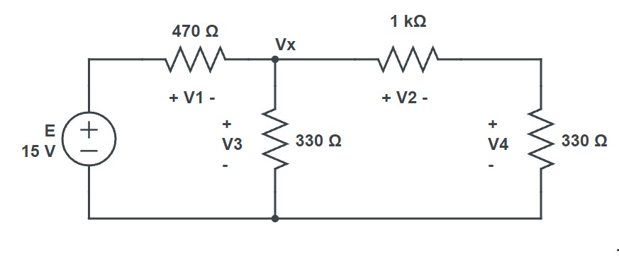
It is possible to define three closed loops in the circuit shown in Figure 5.12 as follows:
4.
Loop 1:
E, R1, R3
Loop 2:
R3, R2, R4
Loop 3:
E, R,R2, R4
Using the da ta you recorded in Table 5.4, determine how well your results demonstrate the
Account for any
validity of Kirchhoff's voltage law around each of the closed loops.
discrepancies between theoretical and experimental results.

Transcribed Image Text:7.
After setting the power supply voltage to 15 V, measure and record the voltages V,V, V3 and
obser ving the polarities shown on the circuit diagram. Complete Table 5.4.
V.
V2-
R, = 4702
R, = 1 K2
Power
R2 = 330 2
R, = 3302
supply
15
Figure 5.12. Measure the voltages to verify Kirchhoff's
voltage law in each loop.
Table 5.4
V1
V2
V3
(V)
(v)
(V)
(v)
9.57
4.08
5.41
1,32
Expert Solution
Step 1

Step by step
Solved in 2 steps with 2 images

Recommended textbooks for you
Introductory Circuit Analysis (13th Edition)
Electrical Engineering
ISBN:
9780133923605
Author:
Robert L. Boylestad
Publisher:
PEARSON

Delmar's Standard Textbook Of Electricity
Electrical Engineering
ISBN:
9781337900348
Author:
Stephen L. Herman
Publisher:
Cengage Learning

Programmable Logic Controllers
Electrical Engineering
ISBN:
9780073373843
Author:
Frank D. Petruzella
Publisher:
McGraw-Hill Education
Introductory Circuit Analysis (13th Edition)
Electrical Engineering
ISBN:
9780133923605
Author:
Robert L. Boylestad
Publisher:
PEARSON
Delmar's Standard Textbook Of Electricity
Electrical Engineering
ISBN:
9781337900348
Author:
Stephen L. Herman
Publisher:
Cengage Learning
Programmable Logic Controllers
Electrical Engineering
ISBN:
9780073373843
Author:
Frank D. Petruzella
Publisher:
McGraw-Hill Education

Fundamentals of Electric Circuits
Electrical Engineering
ISBN:
9780078028229
Author:
Charles K Alexander, Matthew Sadiku
Publisher:
McGraw-Hill Education

Electric Circuits. (11th Edition)
Electrical Engineering
ISBN:
9780134746968
Author:
James W. Nilsson, Susan Riedel
Publisher:
PEARSON

Engineering Electromagnetics
Electrical Engineering
ISBN:
9780078028151
Author:
Hayt, William H. (william Hart), Jr, BUCK, John A.
Publisher:
Mcgraw-hill Education,