5VI below. sion 10 дога Фад 42 81 10.л Ь

Introductory Circuit Analysis (13th Edition)
13th Edition
ISBN:9780133923605
Author:Robert L. Boylestad
Publisher:Robert L. Boylestad
Chapter1: Introduction
Section: Chapter Questions
Problem 1P: Visit your local library (at school or home) and describe the extent to which it provides literature...

Related questions

Concept explainers
KVL and KCL
KVL stands for Kirchhoff voltage law. KVL states that the total voltage drops around the loop in any closed electric circuit is equal to the sum of total voltage drop in the same closed loop.
Sign Convention
Science and technology incorporate some ideas and techniques of their own to understand a system skilfully and easily. These techniques are called conventions. For example: Sign conventions of mirrors are used to understand the phenomenon of reflection and refraction in an easier way.
Question

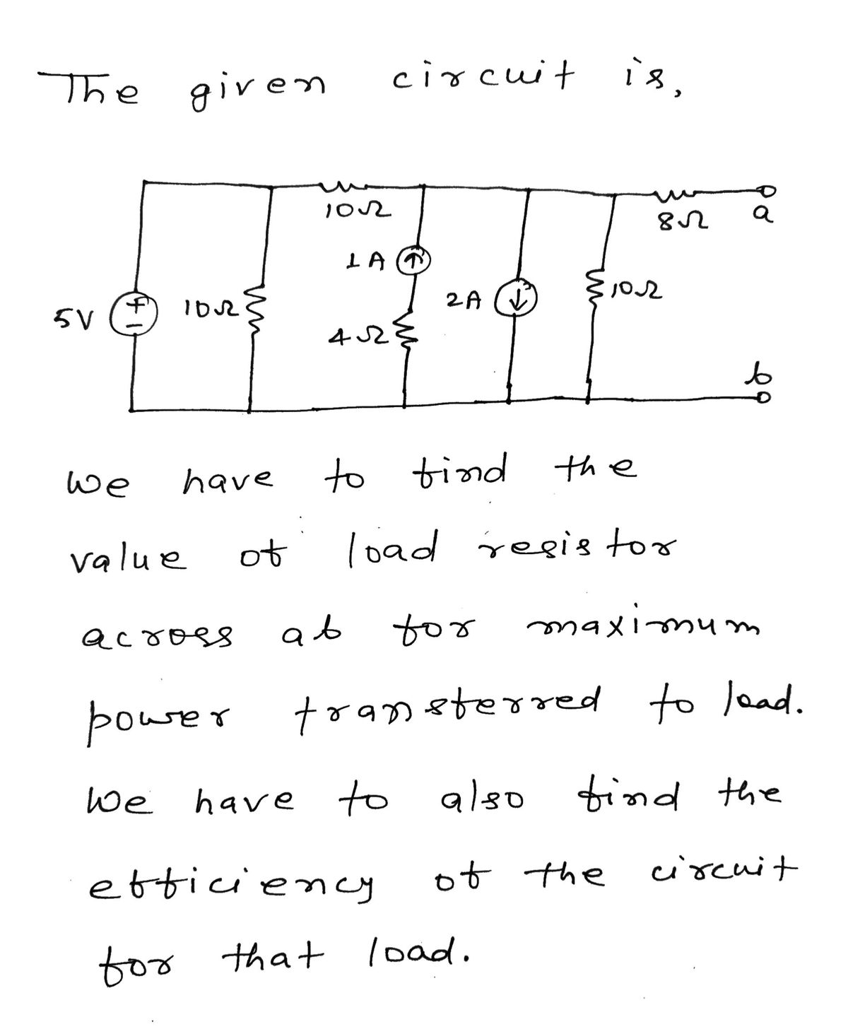
Transcribed Image Text:The image shows an electrical circuit diagram consisting of the following components:
1. A voltage source of 5V.
2. A 10 ohm resistor connected in series with the voltage source.
3. An ammeter displaying a current of 1 A is connected in series and located between two resistors.
4. A 4 ohm resistor in series with the ammeter.
5. A current source providing 2 A, connected in parallel with the 4 ohm resistor and ammeter.
6. Another 10 ohm resistor connected in series with the parallel arrangement.
7. An 8 ohm resistor is connected to the second 10 ohm resistor.
8. The circuit ends at points labeled 'a' and 'b'.
This simple series and parallel circuit can be analyzed to find the voltage across various components and the current flowing through each part. Students may apply Ohm's Law and Kirchhoff's laws to assess the circuit's behavior.

Transcribed Image Text:Sure! Here's the transcription suitable for an educational website:
---
**Problem 9:**
What value of load resistor connected to terminals a and b of problem #7 will give maximum power transferred to the load? What is the efficiency of this circuit expressed as a percentage of total power going to the load?
---
If there were any graphs or diagrams accompanying the text, they would be described in detail to enhance understanding. However, the image provided contains only text.
Expert Solution
Step 1

Step by step
Solved in 3 steps with 3 images

Knowledge Booster


Learn more about
Need a deep-dive on the concept behind this application? Look no further. Learn more about this topic, electrical-engineering and related others by exploring similar questions and additional content below.Recommended textbooks for you
Introductory Circuit Analysis (13th Edition)
Electrical Engineering
ISBN:
9780133923605
Author:
Robert L. Boylestad
Publisher:
PEARSON

Delmar's Standard Textbook Of Electricity
Electrical Engineering
ISBN:
9781337900348
Author:
Stephen L. Herman
Publisher:
Cengage Learning

Programmable Logic Controllers
Electrical Engineering
ISBN:
9780073373843
Author:
Frank D. Petruzella
Publisher:
McGraw-Hill Education
Introductory Circuit Analysis (13th Edition)
Electrical Engineering
ISBN:
9780133923605
Author:
Robert L. Boylestad
Publisher:
PEARSON
Delmar's Standard Textbook Of Electricity
Electrical Engineering
ISBN:
9781337900348
Author:
Stephen L. Herman
Publisher:
Cengage Learning
Programmable Logic Controllers
Electrical Engineering
ISBN:
9780073373843
Author:
Frank D. Petruzella
Publisher:
McGraw-Hill Education

Fundamentals of Electric Circuits
Electrical Engineering
ISBN:
9780078028229
Author:
Charles K Alexander, Matthew Sadiku
Publisher:
McGraw-Hill Education

Electric Circuits. (11th Edition)
Electrical Engineering
ISBN:
9780134746968
Author:
James W. Nilsson, Susan Riedel
Publisher:
PEARSON

Engineering Electromagnetics
Electrical Engineering
ISBN:
9780078028151
Author:
Hayt, William H. (william Hart), Jr, BUCK, John A.
Publisher:
Mcgraw-hill Education,