5.) Sketch the positive root locus for the system shown below. Determine the required value of K so that the control system has critically damped poles. Find the pole locations using this value of K. Estimate the rise time and the steady-state error with a unit-step reference input using this value of K. + s + 4 K s2 + 3s + 2
5.) Sketch the positive root locus for the system shown below. Determine the required value of K so that the control system has critically damped poles. Find the pole locations using this value of K. Estimate the rise time and the steady-state error with a unit-step reference input using this value of K. + s + 4 K s2 + 3s + 2

Introductory Circuit Analysis (13th Edition)
13th Edition
ISBN:9780133923605
Author:Robert L. Boylestad
Publisher:Robert L. Boylestad
Chapter1: Introduction
Section: Chapter Questions
Problem 1P: Visit your local library (at school or home) and describe the extent to which it provides literature...

Related questions
Question

Transcribed Image Text:### Transcription:
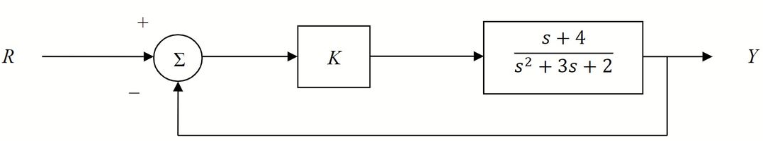
**Problem 5:**
Sketch the positive root locus for the system shown below. Determine the required value of \( K \) so that the control system has critically damped poles. Find the pole locations using this value of \( K \). Estimate the rise time and the steady-state error with a unit-step reference input using this value of \( K \). ~~Use Matlab to plot the unit-step response using this value of \( K \).~~
#### System Diagram:
The system block diagram consists of the following components:
1. **Summation Block (\(\Sigma\)):**
- Inputs: \( R \) (Reference) as the positive input and feedback as the negative input.
2. **Gain Block:**
- Denoted by \( K \).
3. **Transfer Function Block:**
- Transfer Function: \( \frac{s + 4}{s^2 + 3s + 2} \).
- Output: \( Y \).
The system is a closed-loop feedback control system, where the output \( Y \) is fed back into the summation block to compare against the reference input \( R \).
Expert Solution
Step 1
Given the block diagram:
We need to sketch the root locus for the system.
We need to determine the required value of K so that the control system has critically damped poles, we need to find the pole locations using this value of K.
We need to estimate the rise time and the steady-state error with a unit reference input using this value of K.

Step by step
Solved in 4 steps with 2 images

Recommended textbooks for you
Introductory Circuit Analysis (13th Edition)
Electrical Engineering
ISBN:
9780133923605
Author:
Robert L. Boylestad
Publisher:
PEARSON

Delmar's Standard Textbook Of Electricity
Electrical Engineering
ISBN:
9781337900348
Author:
Stephen L. Herman
Publisher:
Cengage Learning

Programmable Logic Controllers
Electrical Engineering
ISBN:
9780073373843
Author:
Frank D. Petruzella
Publisher:
McGraw-Hill Education
Introductory Circuit Analysis (13th Edition)
Electrical Engineering
ISBN:
9780133923605
Author:
Robert L. Boylestad
Publisher:
PEARSON
Delmar's Standard Textbook Of Electricity
Electrical Engineering
ISBN:
9781337900348
Author:
Stephen L. Herman
Publisher:
Cengage Learning
Programmable Logic Controllers
Electrical Engineering
ISBN:
9780073373843
Author:
Frank D. Petruzella
Publisher:
McGraw-Hill Education

Fundamentals of Electric Circuits
Electrical Engineering
ISBN:
9780078028229
Author:
Charles K Alexander, Matthew Sadiku
Publisher:
McGraw-Hill Education

Electric Circuits. (11th Edition)
Electrical Engineering
ISBN:
9780134746968
Author:
James W. Nilsson, Susan Riedel
Publisher:
PEARSON

Engineering Electromagnetics
Electrical Engineering
ISBN:
9780078028151
Author:
Hayt, William H. (william Hart), Jr, BUCK, John A.
Publisher:
Mcgraw-hill Education,