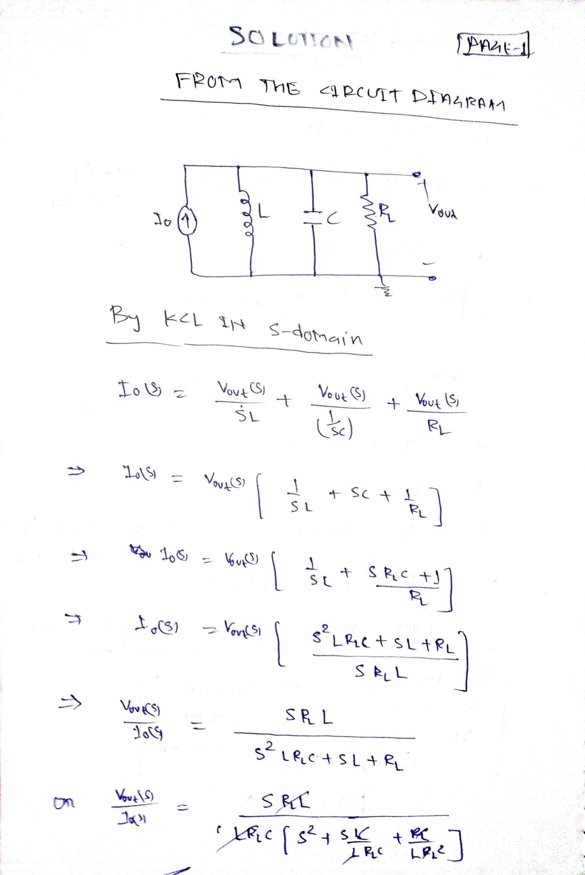
5) Consider the RLC tank circuit shown in Figure 4 being driven by an AC current source. Current Source (→ Imn R_L V_Out a) Calculate the amplitude response Vout as a function of the frequency w of the current source. Use wo = 1/ Figure 4: RLC resonator for prelab Problem PL5. √LC for the resonant frequency (rad/sec). What is the magnitude of the complex amplitude response G(w) = |H(w)|? If the current has amplitude Io, what is the voltage V₁ on resonance at frequency wo? Note that in this case, H(w) = Vout(W)/Io (w), where Io(w) is the current emitted by the current source. b) Calculate the detuning Aw required to reduce G(w) by √√2, which is the 3dB point of the resonator. The detuning is the frequency shift away from the resonant frequency. Use this to determine the bandwidth BW and to calculate the Q of the filter. Express your results in terms of R₁, L, and C. Hint: you will want to set your expression for G(w) = 1/√√2 and evaluate your expression for small changes from the resonance frequency Aw = w-wo, where the detuning Aw is small compared to wo. You should then neglect terms of order (Aw/wo)² and solve for Aw. If you do not do this, your solution is likely to turn into an algebraic mess. Finally, remember that the detuning is only one half the bandwidth, so BW = 2^w.
5) Consider the RLC tank circuit shown in Figure 4 being driven by an AC current source. Current Source (→ Imn R_L V_Out a) Calculate the amplitude response Vout as a function of the frequency w of the current source. Use wo = 1/ Figure 4: RLC resonator for prelab Problem PL5. √LC for the resonant frequency (rad/sec). What is the magnitude of the complex amplitude response G(w) = |H(w)|? If the current has amplitude Io, what is the voltage V₁ on resonance at frequency wo? Note that in this case, H(w) = Vout(W)/Io (w), where Io(w) is the current emitted by the current source. b) Calculate the detuning Aw required to reduce G(w) by √√2, which is the 3dB point of the resonator. The detuning is the frequency shift away from the resonant frequency. Use this to determine the bandwidth BW and to calculate the Q of the filter. Express your results in terms of R₁, L, and C. Hint: you will want to set your expression for G(w) = 1/√√2 and evaluate your expression for small changes from the resonance frequency Aw = w-wo, where the detuning Aw is small compared to wo. You should then neglect terms of order (Aw/wo)² and solve for Aw. If you do not do this, your solution is likely to turn into an algebraic mess. Finally, remember that the detuning is only one half the bandwidth, so BW = 2^w.

Introductory Circuit Analysis (13th Edition)
13th Edition
ISBN:9780133923605
Author:Robert L. Boylestad
Publisher:Robert L. Boylestad
Chapter1: Introduction
Section: Chapter Questions
Problem 1P: Visit your local library (at school or home) and describe the extent to which it provides literature...

Related questions
Question

Transcribed Image Text:5) Consider the RLC tank circuit shown in
Figure 4 being driven by an AC current
source.
Current Source
(→
Imn
R_L
V_Out
a) Calculate the amplitude response
Vout as a function of the frequency
w of the current source. Use wo = 1/
Figure 4: RLC resonator for prelab Problem PL5.
√LC for the resonant frequency (rad/sec). What is the magnitude of the complex
amplitude response G(w) = |H(w)|? If the current has amplitude Io, what is the
voltage Von resonance at frequency wo? Note that in this case, H(w) = Vout(W)/Io
(w), where Io(w) is the current emitted by the current source.
b) Calculate the detuning Aw required to reduce G(w) by √√2, which is the 3dB point of
the resonator. The detuning is the frequency shift away from the resonant frequency.
Use this to determine the bandwidth BW and to calculate the Q of the filter. Express
your results in terms of R₁, L, and C.
Hint: you will want to set your expression for G(w) = 1/√√2 and evaluate your
expression for small changes from the resonance frequency Aw = w-wo, where the
detuning Aw is small compared to wo. You should then neglect terms of order
(Aw/wo)² and solve for Aw. If you do not do this, your solution is likely to turn into
an algebraic mess. Finally, remember that the detuning is only one half the
bandwidth, so BW = 2^w.
Expert Solution
Step 1

Step by step
Solved in 6 steps with 6 images

Knowledge Booster


Learn more about
Need a deep-dive on the concept behind this application? Look no further. Learn more about this topic, electrical-engineering and related others by exploring similar questions and additional content below.Recommended textbooks for you
Introductory Circuit Analysis (13th Edition)
Electrical Engineering
ISBN:
9780133923605
Author:
Robert L. Boylestad
Publisher:
PEARSON

Delmar's Standard Textbook Of Electricity
Electrical Engineering
ISBN:
9781337900348
Author:
Stephen L. Herman
Publisher:
Cengage Learning

Programmable Logic Controllers
Electrical Engineering
ISBN:
9780073373843
Author:
Frank D. Petruzella
Publisher:
McGraw-Hill Education
Introductory Circuit Analysis (13th Edition)
Electrical Engineering
ISBN:
9780133923605
Author:
Robert L. Boylestad
Publisher:
PEARSON
Delmar's Standard Textbook Of Electricity
Electrical Engineering
ISBN:
9781337900348
Author:
Stephen L. Herman
Publisher:
Cengage Learning
Programmable Logic Controllers
Electrical Engineering
ISBN:
9780073373843
Author:
Frank D. Petruzella
Publisher:
McGraw-Hill Education

Fundamentals of Electric Circuits
Electrical Engineering
ISBN:
9780078028229
Author:
Charles K Alexander, Matthew Sadiku
Publisher:
McGraw-Hill Education

Electric Circuits. (11th Edition)
Electrical Engineering
ISBN:
9780134746968
Author:
James W. Nilsson, Susan Riedel
Publisher:
PEARSON

Engineering Electromagnetics
Electrical Engineering
ISBN:
9780078028151
Author:
Hayt, William H. (william Hart), Jr, BUCK, John A.
Publisher:
Mcgraw-hill Education,