4.7K2 1kQ 1kQ V1 + Vo

Introductory Circuit Analysis (13th Edition)
13th Edition
ISBN:9780133923605
Author:Robert L. Boylestad
Publisher:Robert L. Boylestad
Chapter1: Introduction
Section: Chapter Questions
Problem 1P: Visit your local library (at school or home) and describe the extent to which it provides literature...

Related questions

Question
Summing Amp, output voltage of V1 and V2.

Transcribed Image Text:This image illustrates an operational amplifier (op-amp) circuit configured in a differential amplifier setup.
### Description of Components:
- **Voltage Sources**:
- \( v_1 \) and \( v_2 \) are the input voltage sources connected to resistors.
- **Resistors**:
- Two 1kΩ resistors are in series with each input voltage source.
- A 4.7kΩ resistor is connected from the output to the non-inverting input of the op-amp.
- **Operational Amplifier**:
- The op-amp has two inputs: the inverting input (\( v^- \)) and the non-inverting input (\( v^+ \)).
- The input currents at these terminals are \( i^- \) and \( i^+ \) respectively.
- The op-amp outputs a voltage \( v_0 \).
### Explanation of Function:
This differential amplifier setup aims to amplify the difference between the two input voltages (\( v_1 - v_2 \)), using the pairs of resistors as a means to set the gain. The feedback resistor (4.7kΩ) influences the gain and stability of the amplifier. This configuration is commonly used in data acquisition, instrumentation, and signal processing applications.
Expert Solution
Step 1
The output voltage for a Summing Op-amp in inverting mode is given by:
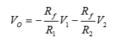
Where,
The feedback resistance is “Rf” which is 4.7 kΩ,
The input resistance to 1st voltage source is “R1” which is 1 kΩ,
The input resistance to 2nd voltage source is “R2” which is 1 kΩ.

Step by step
Solved in 2 steps with 2 images

Knowledge Booster


Learn more about
Need a deep-dive on the concept behind this application? Look no further. Learn more about this topic, electrical-engineering and related others by exploring similar questions and additional content below.Recommended textbooks for you
Introductory Circuit Analysis (13th Edition)
Electrical Engineering
ISBN:
9780133923605
Author:
Robert L. Boylestad
Publisher:
PEARSON

Delmar's Standard Textbook Of Electricity
Electrical Engineering
ISBN:
9781337900348
Author:
Stephen L. Herman
Publisher:
Cengage Learning

Programmable Logic Controllers
Electrical Engineering
ISBN:
9780073373843
Author:
Frank D. Petruzella
Publisher:
McGraw-Hill Education
Introductory Circuit Analysis (13th Edition)
Electrical Engineering
ISBN:
9780133923605
Author:
Robert L. Boylestad
Publisher:
PEARSON
Delmar's Standard Textbook Of Electricity
Electrical Engineering
ISBN:
9781337900348
Author:
Stephen L. Herman
Publisher:
Cengage Learning
Programmable Logic Controllers
Electrical Engineering
ISBN:
9780073373843
Author:
Frank D. Petruzella
Publisher:
McGraw-Hill Education

Fundamentals of Electric Circuits
Electrical Engineering
ISBN:
9780078028229
Author:
Charles K Alexander, Matthew Sadiku
Publisher:
McGraw-Hill Education

Electric Circuits. (11th Edition)
Electrical Engineering
ISBN:
9780134746968
Author:
James W. Nilsson, Susan Riedel
Publisher:
PEARSON

Engineering Electromagnetics
Electrical Engineering
ISBN:
9780078028151
Author:
Hayt, William H. (william Hart), Jr, BUCK, John A.
Publisher:
Mcgraw-hill Education,