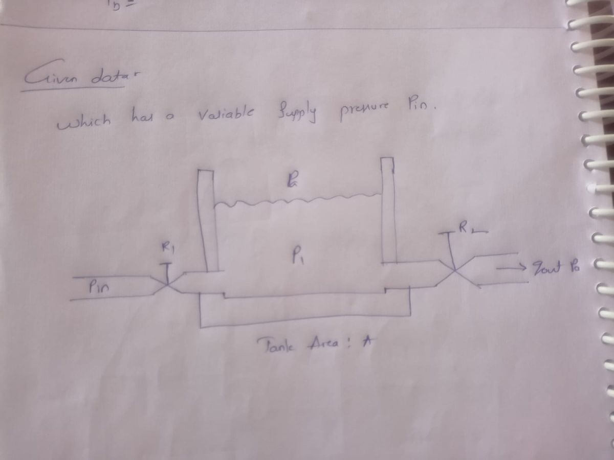
4. Consider the following system, which has a variable supply pressure pin F Pin R₁ P1 Tank Area: A R₂ * gout Pa (a) Find the impedance network that describes this system, considering på as ground. (b) Find the transfer function P₁(s)/Pin (8). (c) Find an equation that the parameters R₁, R₂, A, p, and g should satisfy in order that the step response settling time t, < 10s
4. Consider the following system, which has a variable supply pressure pin F Pin R₁ P1 Tank Area: A R₂ * gout Pa (a) Find the impedance network that describes this system, considering på as ground. (b) Find the transfer function P₁(s)/Pin (8). (c) Find an equation that the parameters R₁, R₂, A, p, and g should satisfy in order that the step response settling time t, < 10s
Introductory Circuit Analysis (13th Edition)
13th Edition
ISBN:9780133923605
Author:Robert L. Boylestad
Publisher:Robert L. Boylestad
Chapter1: Introduction
Section: Chapter Questions
Problem 1P: Visit your local library (at school or home) and describe the extent to which it provides literature...
Related questions
Question
Note that although part c's solution has been given, please show all the work necessary to arrive at that equation. Work is also required for part a and part b.

Transcribed Image Text:# Problem Statement and System Diagram
Consider a system with a variable supply pressure \( p_{in} \). The schematic diagram of the system includes:
- A tank with area \( A \).
- A pressure \( p_1 \) within the tank.
- Fluid flow entering the tank at a point with resistance \( R_1 \) at pressure \( p_{in} \).
- Fluid flow exiting the tank at a point with resistance \( R_2 \), resulting in flow \( q_{out} \).
- Atmospheric pressure \( p_a \) is designated as the reference or ground.
## Tasks
(a) **Impedance Network**
Identify the impedance network describing the system, using \( p_a \) as the ground reference.
(b) **Transfer Function**
Determine the transfer function \( \frac{P_1(s)}{P_{in}(s)} \), where \( P_1(s) \) and \( P_{in}(s) \) are the Laplace transforms of the pressures \( p_1 \) and \( p_{in} \), respectively.
(c) **Settling Time Condition**
Develop an equation involving the parameters \( R_1, R_2, A, \rho, \) and \( g \) to ensure the step response settling time \( t_s < 10s \).
### Diagram Description
The diagram showcases a tank with input and output flows:
- \( R_1 \) represents the resistance to the flow entering the tank under pressure \( p_{in} \).
- \( R_2 \) represents the resistance to the exiting flow \( q_{out} \).
- The tank's pressure \( p_1 \) is governed by these flow dynamics, given the area \( A \) and atmospheric pressure \( p_a \).

Transcribed Image Text:**4.** \(\frac{(R_1 + R_2) \rho g}{R_1 R_2 A} > 0.46\)
In this mathematical expression, we have a fraction on the left side of the inequality:
- **Numerator: (R1 + R2) ρg**
- \(R_1\) and \(R_2\) are variables or constants that likely represent resistance or radii.
- \(\rho\) (rho) could denote density.
- \(g\) is probably the acceleration due to gravity.
- **Denominator: R1 R2 A**
- \(R_1 R_2\) is the product of \(R_1\) and \(R_2\).
- \(A\) may represent an area or another proportionality constant.
The expression asserts that the ratio is greater than 0.46. It's used for analyzing relationships between these variables, potentially in physics or engineering contexts.
Expert Solution
Step 1

Step by step
Solved in 2 steps with 5 images

Recommended textbooks for you

Introductory Circuit Analysis (13th Edition)
Electrical Engineering
ISBN:
9780133923605
Author:
Robert L. Boylestad
Publisher:
PEARSON

Delmar's Standard Textbook Of Electricity
Electrical Engineering
ISBN:
9781337900348
Author:
Stephen L. Herman
Publisher:
Cengage Learning

Programmable Logic Controllers
Electrical Engineering
ISBN:
9780073373843
Author:
Frank D. Petruzella
Publisher:
McGraw-Hill Education

Introductory Circuit Analysis (13th Edition)
Electrical Engineering
ISBN:
9780133923605
Author:
Robert L. Boylestad
Publisher:
PEARSON

Delmar's Standard Textbook Of Electricity
Electrical Engineering
ISBN:
9781337900348
Author:
Stephen L. Herman
Publisher:
Cengage Learning

Programmable Logic Controllers
Electrical Engineering
ISBN:
9780073373843
Author:
Frank D. Petruzella
Publisher:
McGraw-Hill Education

Fundamentals of Electric Circuits
Electrical Engineering
ISBN:
9780078028229
Author:
Charles K Alexander, Matthew Sadiku
Publisher:
McGraw-Hill Education

Electric Circuits. (11th Edition)
Electrical Engineering
ISBN:
9780134746968
Author:
James W. Nilsson, Susan Riedel
Publisher:
PEARSON

Engineering Electromagnetics
Electrical Engineering
ISBN:
9780078028151
Author:
Hayt, William H. (william Hart), Jr, BUCK, John A.
Publisher:
Mcgraw-hill Education,