3.20 Determine the displacements and Green-Lagrange strain components for the deformed configuration shown in Fig. P3.20. The undeformed configuration is shown in dashed lines. Use the suggested form of the deformation mapping, as implied by the deformed configuration. X₂, X₂ -a-B x₂ =q₂X₁ + a₂X², x₂ = b₂ X₁ + b₂ X₂, x₂=X₂. x₁ =q₂X₁ + a₂ X² X₁, X₂ Fig. P3.20
3.20 Determine the displacements and Green-Lagrange strain components for the deformed configuration shown in Fig. P3.20. The undeformed configuration is shown in dashed lines. Use the suggested form of the deformation mapping, as implied by the deformed configuration. X₂, X₂ -a-B x₂ =q₂X₁ + a₂X², x₂ = b₂ X₁ + b₂ X₂, x₂=X₂. x₁ =q₂X₁ + a₂ X² X₁, X₂ Fig. P3.20

Chapter2: Loads On Structures
Section: Chapter Questions
Problem 1P

Related questions

Question
100%

Transcribed Image Text:### Problem Statement:
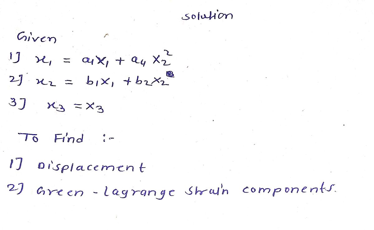
**3.20** Determine the displacements and Green–Lagrange strain components for the deformed configuration shown in Fig. P3.20. The undeformed configuration is shown in dashed lines. Use the suggested form of the deformation mapping, as implied by the deformed configuration.
### Figure Description:
The diagram in Fig. P3.20 illustrates a deformation mapping process. It shows both the undeformed configuration (dashed lines) and the deformed configuration (solid lines) on a Cartesian coordinate system.
Key aspects of the diagram include:
- **Coordinate Axes:**
- \( x_1, X_1 \) and \( x_2, X_2 \) are shown as horizontal and vertical axes on the plane, respectively.
- \( x_3, X_3 \) is indicated, representing an axis perpendicular to the \( x_1, x_2 \) plane.
- **Points and Lines:**
- Points \( A \), \( B \), \( C \), and \( D \) are marked on the plane, defining the boundaries of both undeformed (dashed) and deformed (solid) shapes.
- The distance \( a \) represents the length from \( A \) to \( B \).
- The height \( b \) represents the length from \( A \) to \( D \).
- **Deformation Variables:**
- \( x_1 = a_1 X_1 + a_4 X_2^2 \)
- \( x_2 = b_1 X_1 + b_2 X_2 \)
- \( x_3 = X_3 \)
These equations describe the mapping of the initial undeformed coordinates \( X_1, X_2, X_3 \) to the deformed coordinates \( x_1, x_2, x_3 \).
### Additional Elements:
- The deformation is suggested to consider the transformation outlined by the equations, implying elongation and curvature as shown by the diagram's solid lines.
- The dimensions \( e \) on both the horizontal and vertical axes signify the amount of displacement in each direction.
This transcribed content would be suitable for inclusion in an educational context, explaining the process of determining displacements and strains due to deformation.
Expert Solution
Step 1

Step by step
Solved in 2 steps with 2 images

Knowledge Booster


Learn more about
Need a deep-dive on the concept behind this application? Look no further. Learn more about this topic, civil-engineering and related others by exploring similar questions and additional content below.Recommended textbooks for you

Structural Analysis (10th Edition)
Civil Engineering
ISBN:
9780134610672
Author:
Russell C. Hibbeler
Publisher:
PEARSON

Principles of Foundation Engineering (MindTap Cou…
Civil Engineering
ISBN:
9781337705028
Author:
Braja M. Das, Nagaratnam Sivakugan
Publisher:
Cengage Learning
Structural Analysis (10th Edition)
Civil Engineering
ISBN:
9780134610672
Author:
Russell C. Hibbeler
Publisher:
PEARSON
Principles of Foundation Engineering (MindTap Cou…
Civil Engineering
ISBN:
9781337705028
Author:
Braja M. Das, Nagaratnam Sivakugan
Publisher:
Cengage Learning

Fundamentals of Structural Analysis
Civil Engineering
ISBN:
9780073398006
Author:
Kenneth M. Leet Emeritus, Chia-Ming Uang, Joel Lanning
Publisher:
McGraw-Hill Education


Traffic and Highway Engineering
Civil Engineering
ISBN:
9781305156241
Author:
Garber, Nicholas J.
Publisher:
Cengage Learning