3- For the plane truss with an inclined support shown below, solve for the nodal displacements and element stresses in the bars. Let A = 2 in², E = 30 x 10 psi, and L = 30 in. fr L 2 0-0 ********* 2000 lb
3- For the plane truss with an inclined support shown below, solve for the nodal displacements and element stresses in the bars. Let A = 2 in², E = 30 x 10 psi, and L = 30 in. fr L 2 0-0 ********* 2000 lb

Elements Of Electromagnetics
7th Edition
ISBN:9780190698614
Author:Sadiku, Matthew N. O.
Publisher:Sadiku, Matthew N. O.
ChapterMA: Math Assessment
Section: Chapter Questions
Problem 1.1MA

Related questions

Question
This is

Transcribed Image Text:**Problem Statement:**
For the plane truss with an inclined support shown below, solve for the nodal displacements and element stresses in the bars. Let \( A = 2 \, \text{in}^2 \), \( E = 30 \times 10^6 \, \text{psi} \), and \( L = 30 \, \text{in} \).
**Diagram Explanation:**
The diagram illustrates a simple truss system with three nodes (1, 2, and 3) and two members (bars) of equal length \( L \). Node 1 is located at the bottom left and is connected to an inclined support, which provides resistance to movement. Node 2 is located at the top right and has a vertical external load of 2000 lb applied in the downward direction. Node 3 is located on the vertical member to the left, where another horizontal member extends to Node 2.
- **Node Details:**
- Node 1: The foundation is fixed, preventing any displacement in the horizontal or vertical directions.
- Node 2: Connected to Node 1 and Node 3, subjected to a vertical 2000 lb load.
- Node 3: The topmost node, supported horizontally on the left side.
The task is to calculate the displacements and stresses using the given parameters.
Expert Solution
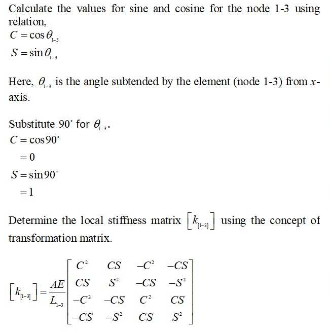
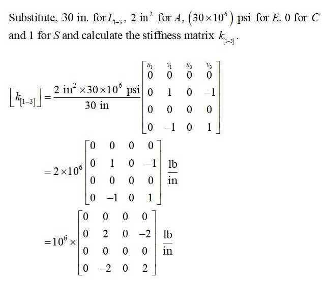
Step 1: For the node 1-3

Step by step
Solved in 5 steps with 17 images

Knowledge Booster


Learn more about
Need a deep-dive on the concept behind this application? Look no further. Learn more about this topic, mechanical-engineering and related others by exploring similar questions and additional content below.Recommended textbooks for you
Elements Of Electromagnetics
Mechanical Engineering
ISBN:
9780190698614
Author:
Sadiku, Matthew N. O.
Publisher:
Oxford University Press

Mechanics of Materials (10th Edition)
Mechanical Engineering
ISBN:
9780134319650
Author:
Russell C. Hibbeler
Publisher:
PEARSON

Thermodynamics: An Engineering Approach
Mechanical Engineering
ISBN:
9781259822674
Author:
Yunus A. Cengel Dr., Michael A. Boles
Publisher:
McGraw-Hill Education
Elements Of Electromagnetics
Mechanical Engineering
ISBN:
9780190698614
Author:
Sadiku, Matthew N. O.
Publisher:
Oxford University Press
Mechanics of Materials (10th Edition)
Mechanical Engineering
ISBN:
9780134319650
Author:
Russell C. Hibbeler
Publisher:
PEARSON
Thermodynamics: An Engineering Approach
Mechanical Engineering
ISBN:
9781259822674
Author:
Yunus A. Cengel Dr., Michael A. Boles
Publisher:
McGraw-Hill Education

Control Systems Engineering
Mechanical Engineering
ISBN:
9781118170519
Author:
Norman S. Nise
Publisher:
WILEY

Mechanics of Materials (MindTap Course List)
Mechanical Engineering
ISBN:
9781337093347
Author:
Barry J. Goodno, James M. Gere
Publisher:
Cengage Learning

Engineering Mechanics: Statics
Mechanical Engineering
ISBN:
9781118807330
Author:
James L. Meriam, L. G. Kraige, J. N. Bolton
Publisher:
WILEY