22.6 Equivalent Circuit (Iron- core Transformer) Ep 10/11 www moo Rp www Rp2 N N 000 ell 000 Xs www R₂ www-l E, R₁ CL


Three-Phase Transformers
Three-segment transformers are a type of transformer used to transform voltages of electrical systems into three ranges. Two type transformers are shell-type transformer and core type transformer. In brief, it could be described because of the exquisite kinds of configurations.
Transformer
Ever since electricity has been created, people have started using it in its entirety. We see many types of Transformers in the neighborhoods. Some are smaller in size and some are very large. They are used according to their requirements. Many of us have seen the electrical transformer but they do not know what work they are engaged in.
How to calculate total Z and R in the circuit?
Please answer in typing format solution please only typing format please

Given circuit:
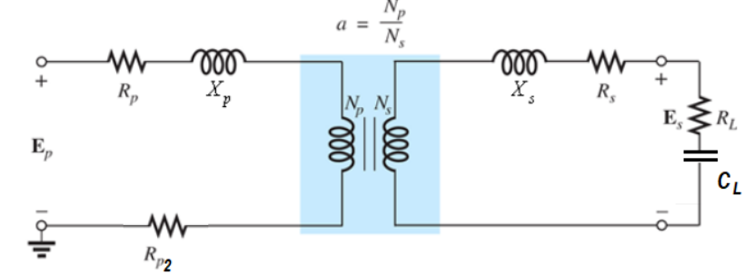
Asked to find the total impedance and total resistance of the transformer?

Step by step
Solved in 3 steps with 6 images


