21 Find v1,v2, and v3 using node analysis ia ww 5Ω 9v +1 22 ww 1Ω V3
21 Find v1,v2, and v3 using node analysis ia ww 5Ω 9v +1 22 ww 1Ω V3

Introductory Circuit Analysis (13th Edition)
13th Edition
ISBN:9780133923605
Author:Robert L. Boylestad
Publisher:Robert L. Boylestad
Chapter1: Introduction
Section: Chapter Questions
Problem 1P: Visit your local library (at school or home) and describe the extent to which it provides literature...

Related questions

Question

Transcribed Image Text:**Transcription and Explanation for Educational Website**
---
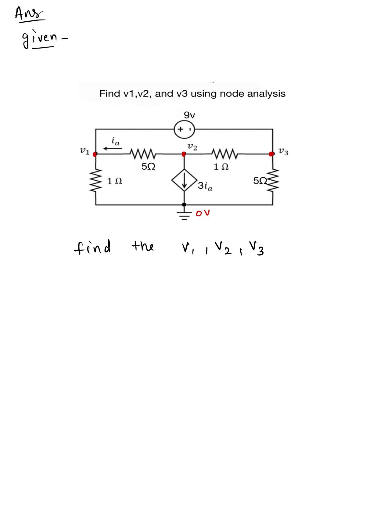
**Objective:** Determine the voltages \( v_1, v_2, \) and \( v_3 \) using node analysis in an electrical circuit.
**Circuit Description:**
The diagram represents an electrical circuit with the following components:
1. **Voltage Source:**
- A 9V voltage source is present in series.
2. **Resistors:**
- Resistor of 1Ω connected at node \( v_1 \).
- Resistor of 5Ω between nodes \( v_1 \) and \( v_2 \).
- Resistor of 1Ω between nodes \( v_2 \) and \( v_3 \).
- Resistor of 5Ω connected at node \( v_3 \).
3. **Current Source:**
- A controlled current source depicted as \( 3i_a \), which depends on the current \( i_a \) through the 1Ω resistor connected to \( v_1 \).
4. **Nodes:**
- Node \( v_1 \) is connected to a 1Ω resistor and a 5Ω resistor.
- Node \( v_2 \) is connected to the 9V source, the same 5Ω resistor as part of the path, another 1Ω resistor leading to \( v_3 \), and a dependent current source.
- Node \( v_3 \) is connected to a 5Ω resistor and forms part of the loop with the other resistors and voltage source.
**Instructions:**
1. **Node Analysis Method:**
- Identify all nodes: \( v_1, v_2, v_3 \).
- Apply Kirchhoff's Current Law (KCL) at each node.
- Express the currents in terms of the node voltages.
- Solve the resulting equations to find the unknown voltages \( v_1, v_2, \) and \( v_3 \).
This circuit involves both independent and dependent sources, which requires calculating dependent variables based on currents through specified elements like \( i_a \).
**Analysis:**
- **Node \( v_1 \):** Analyze the sum of currents leaving or entering the node including \( i_a \).
- **Node \( v_2 \):** Include contributions from the voltage source and account for the controlled current source.
- **Node \( v_
Expert Solution
Step 1

Step by step
Solved in 3 steps with 3 images

Knowledge Booster


Learn more about
Need a deep-dive on the concept behind this application? Look no further. Learn more about this topic, electrical-engineering and related others by exploring similar questions and additional content below.Recommended textbooks for you
Introductory Circuit Analysis (13th Edition)
Electrical Engineering
ISBN:
9780133923605
Author:
Robert L. Boylestad
Publisher:
PEARSON

Delmar's Standard Textbook Of Electricity
Electrical Engineering
ISBN:
9781337900348
Author:
Stephen L. Herman
Publisher:
Cengage Learning

Programmable Logic Controllers
Electrical Engineering
ISBN:
9780073373843
Author:
Frank D. Petruzella
Publisher:
McGraw-Hill Education
Introductory Circuit Analysis (13th Edition)
Electrical Engineering
ISBN:
9780133923605
Author:
Robert L. Boylestad
Publisher:
PEARSON
Delmar's Standard Textbook Of Electricity
Electrical Engineering
ISBN:
9781337900348
Author:
Stephen L. Herman
Publisher:
Cengage Learning
Programmable Logic Controllers
Electrical Engineering
ISBN:
9780073373843
Author:
Frank D. Petruzella
Publisher:
McGraw-Hill Education

Fundamentals of Electric Circuits
Electrical Engineering
ISBN:
9780078028229
Author:
Charles K Alexander, Matthew Sadiku
Publisher:
McGraw-Hill Education

Electric Circuits. (11th Edition)
Electrical Engineering
ISBN:
9780134746968
Author:
James W. Nilsson, Susan Riedel
Publisher:
PEARSON

Engineering Electromagnetics
Electrical Engineering
ISBN:
9780078028151
Author:
Hayt, William H. (william Hart), Jr, BUCK, John A.
Publisher:
Mcgraw-hill Education,