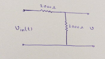
2.000 Ω ww 1.000 Ω ww Vin(t) 2,000 Ω 10 μF Vour()


a. Determine the frequency response
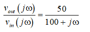
Vout( jω)/Vin( jω) for the circuit of Figure.
b. Plot the magnitude and phase of the circuit for
frequencies between 10 and 107 rad/s on graph
paper, with a linear scale for frequency.
c. Repeat part b, using semilog paper. (Place the
frequency on the logarithmic axis.)
d. Plot the magnitude response on semilog paper with
magnitude in decibels.

Hello. Since your question has multiple sub-parts, we will solve first three sub-parts for you. If you want remaining sub-parts to be solved, then please resubmit the whole question and specify those sub-parts you want us to solve.
Part a:
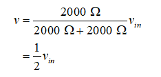
Divide the circuit into the attenuator and the low-pass filter and draw the circuit diagram for the attenuator,
Apply the voltage divider rule and calculate the voltage across 2000 Ω,
Draw the circuit diagram for the low-pass filter,
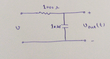
Write the expression for the transfer function of the low-pass filter,
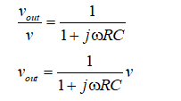
Substitute the known parameter,
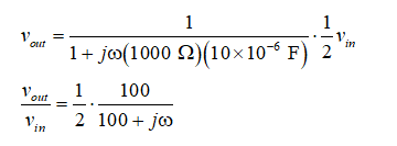
Thus, the frequency response for the circuit is calculated as,

Step by step
Solved in 8 steps with 13 images


