2. The component shown always breaks at point C, which is just to the right of the contact point of the roller at B. Find the internal forces in terms of shear, normal and bending to show why this is. 150 mm -250 mm- 400 N A OB 125 mm 500 N 110 mm 80 N•m
2. The component shown always breaks at point C, which is just to the right of the contact point of the roller at B. Find the internal forces in terms of shear, normal and bending to show why this is. 150 mm -250 mm- 400 N A OB 125 mm 500 N 110 mm 80 N•m

Elements Of Electromagnetics
7th Edition
ISBN:9780190698614
Author:Sadiku, Matthew N. O.
Publisher:Sadiku, Matthew N. O.
ChapterMA: Math Assessment
Section: Chapter Questions
Problem 1.1MA

Related questions
Question

Transcribed Image Text:### Problem Description
The component shown always breaks at point C, which is just to the right of the contact point of the roller at B. Find the internal forces in terms of shear, normal, and bending to show why this is.
### Diagram Explanation
- **Diagram Overview**: The diagram depicts an L-shaped beam subjected to various forces and moments.
- **Beam Structure**:
- The horizontal arm extends 400 mm from point A through point B to point C.
- The vertical section starts at the end of the horizontal arm at C and extends downward.
- The beam makes an L-shape at the corner where it turns downwards.
- **Forces and Dimensions**:
- **Support at A**: A fixed support (triangle symbol) is indicated, which can prevent both translation and rotation.
- **Roller at B**: A roller support is present, which allows for horizontal movement. It is positioned 150 mm from A.
- **External Forces**:
- **400 N**: A downward force acts vertically at point C.
- **500 N**: A horizontal force acts to the right on the vertical section, 125 mm below point C.
- **80 N·m**: A clockwise moment is applied at the bottom of the vertical section.
- **Distances**:
- The distance from A to B is 150 mm, while from B to C is 250 mm.
- The vertical section is 110 mm.
### Task
Calculate the internal forces at the beam's critical point, C:
- **Shear Force**: Analyze forces causing sliding failure along the beam cross-section.
- **Normal Force**: Measure axial forces affecting the beam.
- **Bending Moment**: Evaluate moment forces causing the beam to bend and potentially fail.
### Objective
Determine why breaking consistently occurs at point C, just past the roller. Analyze the contributing internal forces to explain this failure location.
Expert Solution
Step 1
The component always breaks at point C, which is just right of the contact point of the roller at B. So, draw the free-body diagram of the section which is just right of the contact point of the roller at B as follows:
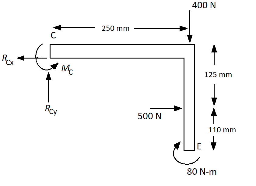
Here, the reaction force at C in the horizontal direction is RCx, the reaction force at C in the vertical direction is RCy and the moment reaction at C is MC.
Step 2
Consider the equilibrium of force in the horizontal direction,
Consider the equilibrium of force in the vertical direction,
Calculate the moment reaction at C,
Step 3
Therefore, the internal forces in terms of shear, normal, and bending are,

Step by step
Solved in 5 steps with 2 images

Knowledge Booster


Learn more about
Need a deep-dive on the concept behind this application? Look no further. Learn more about this topic, mechanical-engineering and related others by exploring similar questions and additional content below.Recommended textbooks for you
Elements Of Electromagnetics
Mechanical Engineering
ISBN:
9780190698614
Author:
Sadiku, Matthew N. O.
Publisher:
Oxford University Press

Mechanics of Materials (10th Edition)
Mechanical Engineering
ISBN:
9780134319650
Author:
Russell C. Hibbeler
Publisher:
PEARSON

Thermodynamics: An Engineering Approach
Mechanical Engineering
ISBN:
9781259822674
Author:
Yunus A. Cengel Dr., Michael A. Boles
Publisher:
McGraw-Hill Education
Elements Of Electromagnetics
Mechanical Engineering
ISBN:
9780190698614
Author:
Sadiku, Matthew N. O.
Publisher:
Oxford University Press
Mechanics of Materials (10th Edition)
Mechanical Engineering
ISBN:
9780134319650
Author:
Russell C. Hibbeler
Publisher:
PEARSON
Thermodynamics: An Engineering Approach
Mechanical Engineering
ISBN:
9781259822674
Author:
Yunus A. Cengel Dr., Michael A. Boles
Publisher:
McGraw-Hill Education

Control Systems Engineering
Mechanical Engineering
ISBN:
9781118170519
Author:
Norman S. Nise
Publisher:
WILEY

Mechanics of Materials (MindTap Course List)
Mechanical Engineering
ISBN:
9781337093347
Author:
Barry J. Goodno, James M. Gere
Publisher:
Cengage Learning

Engineering Mechanics: Statics
Mechanical Engineering
ISBN:
9781118807330
Author:
James L. Meriam, L. G. Kraige, J. N. Bolton
Publisher:
WILEY