2. Draw the shear and moment diagrams for each member of the frame. T 3' 5' W= = 2 kips/ft 4'
2. Draw the shear and moment diagrams for each member of the frame. T 3' 5' W= = 2 kips/ft 4'

Chapter2: Loads On Structures
Section: Chapter Questions
Problem 1P

Related questions
Question
Draw the shear and moment diagrams for each member of the frame.

Transcribed Image Text:**Problem 2:**
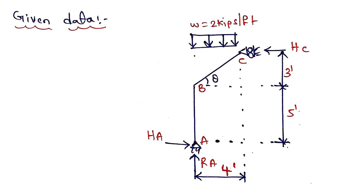
**Task:** Draw the shear and moment diagrams for each member of the frame.
**Description of the Diagram:**
The diagram presents a structural frame consisting of two members, AB and BC. The frame is subjected to a uniformly distributed load (UDL) along member BC.
- The distributed load, \( w \), is 2 kips/ft acting downward along member BC.
- Member AB is vertical, measuring 8 feet in total height (split into 5 feet from A to B, and 3 feet from B to the top).
- Member BC is horizontal, extending 4 feet from B to C.
- The support at A is a hinge or pin, and the support at C is a roller.
**Key Points:**
- The load on BC will generate shear forces and bending moments that need to be calculated and depicted in their respective diagrams.
- The joint at B is a point of moment transfer between members.
- The goal is to obtain the internal shear and moment at different points for both members after considering the equilibrium of forces and moments.
Expert Solution
Step 1

Step by step
Solved in 4 steps with 4 images

Knowledge Booster


Learn more about
Need a deep-dive on the concept behind this application? Look no further. Learn more about this topic, civil-engineering and related others by exploring similar questions and additional content below.Recommended textbooks for you

Structural Analysis (10th Edition)
Civil Engineering
ISBN:
9780134610672
Author:
Russell C. Hibbeler
Publisher:
PEARSON

Principles of Foundation Engineering (MindTap Cou…
Civil Engineering
ISBN:
9781337705028
Author:
Braja M. Das, Nagaratnam Sivakugan
Publisher:
Cengage Learning
Structural Analysis (10th Edition)
Civil Engineering
ISBN:
9780134610672
Author:
Russell C. Hibbeler
Publisher:
PEARSON
Principles of Foundation Engineering (MindTap Cou…
Civil Engineering
ISBN:
9781337705028
Author:
Braja M. Das, Nagaratnam Sivakugan
Publisher:
Cengage Learning

Fundamentals of Structural Analysis
Civil Engineering
ISBN:
9780073398006
Author:
Kenneth M. Leet Emeritus, Chia-Ming Uang, Joel Lanning
Publisher:
McGraw-Hill Education


Traffic and Highway Engineering
Civil Engineering
ISBN:
9781305156241
Author:
Garber, Nicholas J.
Publisher:
Cengage Learning