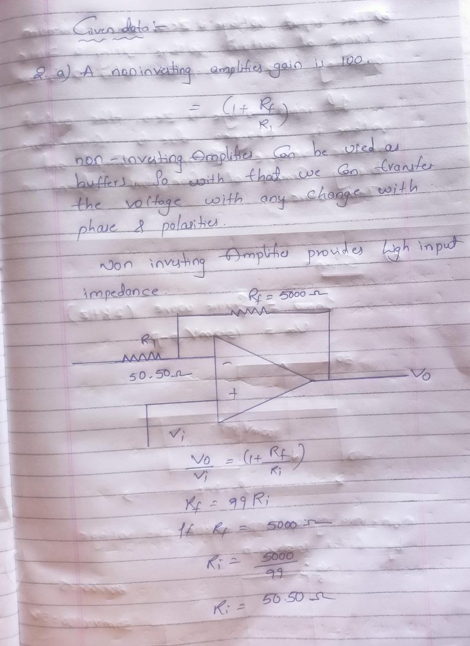
2. a. Design a noninverting amplifier for a gain of 100. What advantage has this design over the inverting configuration? b. If the input voltage is zero, what is the maximum range of output voltage using a 741C operating at a temperature between 0 to 70C7 e: If the input is a 2 kHz square wave of amplitude 100mVp-p, sketch the shape of the output voltage over time. d. If this input in e above has a source resistance of 10kohm, how will the output be affected?


Power Amplifier
The power amplifier is an electronic amplifier designed to maximize the signal strength of a given input. The input signal strength is enhanced to a high enough level to drive output devices such as speakers, headphones, RF (Radio frequency) transmitters, etc. Unlike voltage / current amplifiers, the power amplifier is designed to drive core loads directly and is used as a storage block in the amplifier series.
Maximum Efficiency Criterion
In every field of engineering, there is a tremendous use of the machine and all those machines are equipped for their popular work efficiency so it very much important for operation engineers to monitor the efficiency of the machine, planning engineers to check out the efficiency of the machine before installing the machine and design engineers to design machine for higher efficiency than and then the utility will procure their products that will ultimately lead to profit and loss of the company. It indicates the importance of efficiency right from the initial stage as manufacturing units, intermediate stage as planning coordinators, and end-users stage as a utility.
2 all parts please will give like

2.Solution:

Step by step
Solved in 4 steps with 4 images


