2 kN 39 mA 8 kQ 2 kQ 14 mA ( ↑ 4 k. 4 k2 v

Introductory Circuit Analysis (13th Edition)
13th Edition
ISBN:9780133923605
Author:Robert L. Boylestad
Publisher:Robert L. Boylestad
Chapter1: Introduction
Section: Chapter Questions
Problem 1P: Visit your local library (at school or home) and describe the extent to which it provides literature...

Related questions
Question
find voltage v

Transcribed Image Text:### Circuit Analysis with Current and Resistors
This diagram illustrates a circuit composed of current sources and resistors in series.
#### Components:
- **Current Sources:**
- **39 mA:** Positioned at the start of the circuit, flowing into the path with the resistors.
- **14 mA:** Placed between two resistors in the middle of the circuit, injecting current into the circuit.
- **Resistors:**
- **8 kΩ:** Connected immediately after the first current source (39 mA).
- **2 kΩ:** Positioned next after the 8 kΩ resistor.
- **4 kΩ:** Placed after the 2 kΩ resistor.
- **2 kΩ:** Positioned after the second current source (14 mA) and paired serially with another 4 kΩ resistor.
- **4 kΩ:** Situated at the end of the circuit path, connected in series with the preceding 2 kΩ resistor.
#### Circuit Notation:
- A potential difference is marked across the final 4 kΩ resistor, indicated by the voltage symbol \( v \) with positive and negative terminals marked.
### Explanation:
- The circuit shows a serial configuration where the current sources are directing currents through the resistors, impacting the voltage drop across each resistor.
- The combination of different resistances and the influence of the current sources will determine the overall current flow and potential differences across the circuit components, useful for practical circuit analysis.
This schematic serves as an example for understanding the interaction between components in circuits and analyzing potential drops and current distribution in electrical engineering studies.
Expert Solution
Step 1
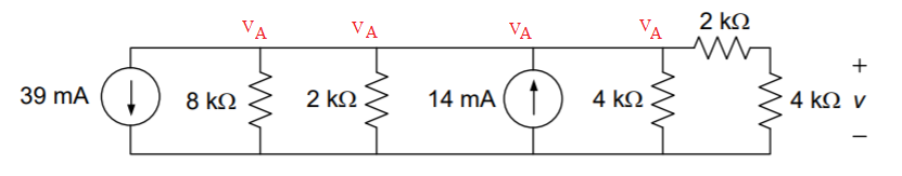
Fig: Given circuit diagram
Assume that voltage at the node at 'A' is VA
Apply KCL at node A

Step by step
Solved in 2 steps with 1 images

Recommended textbooks for you
Introductory Circuit Analysis (13th Edition)
Electrical Engineering
ISBN:
9780133923605
Author:
Robert L. Boylestad
Publisher:
PEARSON

Delmar's Standard Textbook Of Electricity
Electrical Engineering
ISBN:
9781337900348
Author:
Stephen L. Herman
Publisher:
Cengage Learning

Programmable Logic Controllers
Electrical Engineering
ISBN:
9780073373843
Author:
Frank D. Petruzella
Publisher:
McGraw-Hill Education
Introductory Circuit Analysis (13th Edition)
Electrical Engineering
ISBN:
9780133923605
Author:
Robert L. Boylestad
Publisher:
PEARSON
Delmar's Standard Textbook Of Electricity
Electrical Engineering
ISBN:
9781337900348
Author:
Stephen L. Herman
Publisher:
Cengage Learning
Programmable Logic Controllers
Electrical Engineering
ISBN:
9780073373843
Author:
Frank D. Petruzella
Publisher:
McGraw-Hill Education

Fundamentals of Electric Circuits
Electrical Engineering
ISBN:
9780078028229
Author:
Charles K Alexander, Matthew Sadiku
Publisher:
McGraw-Hill Education

Electric Circuits. (11th Edition)
Electrical Engineering
ISBN:
9780134746968
Author:
James W. Nilsson, Susan Riedel
Publisher:
PEARSON

Engineering Electromagnetics
Electrical Engineering
ISBN:
9780078028151
Author:
Hayt, William H. (william Hart), Jr, BUCK, John A.
Publisher:
Mcgraw-hill Education,