2) In the circuit below find: 1₁= 1₂= 13= V= P from source= Q from source= Amps Amps Amps Volts Watts VARS 500 Z0° V Į₂₁ 6 Ω 1002 10Ω THE www
2) In the circuit below find: 1₁= 1₂= 13= V= P from source= Q from source= Amps Amps Amps Volts Watts VARS 500 Z0° V Į₂₁ 6 Ω 1002 10Ω THE www
Chapter29: Service-entrance Calculations
Section: Chapter Questions
Problem 3R: a. What is the ampere rating of the circuits that are provided for the small-appliance loads? _____...
Related questions
Question

Transcribed Image Text:### Problem Statement
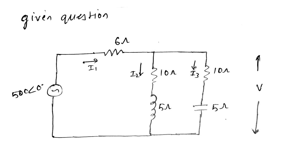
2) In the circuit below, find:
- \( i_1 = \) __________ Amps
- \( i_2 = \) __________ Amps
- \( i_3 = \) __________ Amps
- \( V = \) __________ Volts
- \( P \) from source = __________ Watts
- \( Q \) from source = __________ VARs
### Circuit Diagram Details
- A voltage source of \( 500 \angle 0^\circ \) V is connected in series with a 6 Ω resistor through which current \( I_1 \) flows.
- Current \( I_1 \) splits into two parallel branches:
- The first branch has a series combination of a 10 Ω resistor and a 5 Ω inductor, through which current \( I_2 \) flows.
- The second branch has a series combination of a 10 Ω resistor and a 5 Ω capacitor, through which current \( I_3 \) flows.
- The voltage across the parallel branches is denoted as \( V \).
The task is to calculate the currents \( i_1, i_2, i_3 \), the voltage \( V \) across the parallel branches, and the real and reactive power (\( P \) and \( Q \)) from the source.
Expert Solution
Step 1

Step by step
Solved in 3 steps with 3 images

Knowledge Booster
Learn more about
Need a deep-dive on the concept behind this application? Look no further. Learn more about this topic, electrical-engineering and related others by exploring similar questions and additional content below.Recommended textbooks for you

EBK ELECTRICAL WIRING RESIDENTIAL
Electrical Engineering
ISBN:
9781337516549
Author:
Simmons
Publisher:
CENGAGE LEARNING - CONSIGNMENT

Power System Analysis and Design (MindTap Course …
Electrical Engineering
ISBN:
9781305632134
Author:
J. Duncan Glover, Thomas Overbye, Mulukutla S. Sarma
Publisher:
Cengage Learning

Electricity for Refrigeration, Heating, and Air C…
Mechanical Engineering
ISBN:
9781337399128
Author:
Russell E. Smith
Publisher:
Cengage Learning

EBK ELECTRICAL WIRING RESIDENTIAL
Electrical Engineering
ISBN:
9781337516549
Author:
Simmons
Publisher:
CENGAGE LEARNING - CONSIGNMENT

Power System Analysis and Design (MindTap Course …
Electrical Engineering
ISBN:
9781305632134
Author:
J. Duncan Glover, Thomas Overbye, Mulukutla S. Sarma
Publisher:
Cengage Learning

Electricity for Refrigeration, Heating, and Air C…
Mechanical Engineering
ISBN:
9781337399128
Author:
Russell E. Smith
Publisher:
Cengage Learning