1Ω ww o a 24 V (+ o b 2Ω 5Ω 2 A
Q: R, = 3 n R, = 6 N V = 24 V R, = 6 Please use this image to answer Questions #41 through #43. The…
A: The circuit is shown below.
Q: 5) Three capacitors (C₁, C2, and C3) are arranged in the circuit shown in the figure with the power…
A: Given Capacitors of Capacitance are C1, C2 and C3 are connected as shown in the figure. Voltage…
Q: > Macmillan Learning In the circuit shown, the potential difference VA VB = 16.0 V and the…
A: VA=VB= 16V R1=R2=R3=R4= 195 ohm Find IA and IB
Q: For the circuit shown in Figure 3: + V1 9.V A S1 B R1 1k92 C1 470μF Figure 3: Circuit diagram for…
A: The resistance R1=1 kΩ=103 ΩThe capacitance C1=470 μF=470×10-6 F
Q: In the circuit shown in the figure below, C1=26μF, C2=22μF, C3=31μF, and a voltage Vab=48V is…
A:
Q: Give a simple example of how the potential difference would be measured in a circuit.
A:
Q: Answer the following questions using the circuit shown below, What is the total resistance of the…
A:
Q: 2) Consider the Circuit below. Determine the equivalent capacitance of the circuit and the charges…
A: The objective is to determine the total energy stored in the circuit
Q: electric energy contained in the equivalent capacitor
A:
Q: Answer the questions
A: Explanation of Total Voltage in Series and Parallel ConnectionsIn the given example, you have four…
Q: Consider the figure below, which shows a circuit only containing static electric fields. Given the…
A:
Q: Determine the total equivalent capacitance C of the circuit below when the capacitances are C1 =…
A:
Q: In the circuit below, V. = 8 V, V = 43 V, R = 7 2, & R2 = 2 2. Determine the current through R1, R2,…
A:
Q: 4 20 V 123 4V
A: Given: The emf of the cell is given as The resistance in the circuit is given as
Q: the reading would be on the voltmeter
A:
Q: What is the equivalent resistance of a the following 3 resistors: R1 = 12 Ohms R2 = 14 Ohms R3 =…
A: The equivalent resistance of the parallel connection of the resistors is given by, 1Req,p=1R1+1R3…
Q: The diagram at the right shows two identical resistors - R₁ and R₂ - placed in a circuit with a…
A: The given circuit is shown below.
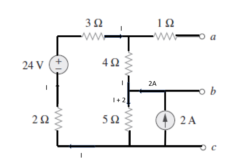
Determine the voltages between points a-b and b-c in the electrical circuit shown in the following figure:

Solution:

Step by step
Solved in 3 steps with 4 images

- a) For the circuit shown below, calculate i) Total capacitance ii) Total charge on 20 uF capacitor2) The circuit shown contains the following three resistors wired to a 6 V battery: R₁ = 652 R₂ = 852 R3 = 492 a) Calculate the equivalent resistance of the circuit. (2) b) Calculate the voltage across R3. (2) www R₁ Page 2 R₂ R3What is the potential difference ΔVΔ� across the unknown element in the circuit shown in the figure? Express your answer as if traveling across the element in the direction shown in the figure. (Figure 6)
- Imagine you have a Buzzer BZ1 with a resistance of 5600 and two lamps L1 and L2 with a resistance of 200 each connected in series to a Battery of 6 Volt as shown in the diagram below BZ1 - 560 Ohms. 6V L1 20 Ohms L2 - 20 Ohms Calculate the power of the Buzzer BZ1, the Lamps L1 and L2 and the power of the BatteryHow to solve this question