192 www B 2A A 12V M 3A m G E 3A www D 19 SA 10V ет H 11 w

Introductory Circuit Analysis (13th Edition)
13th Edition
ISBN:9780133923605
Author:Robert L. Boylestad
Publisher:Robert L. Boylestad
Chapter1: Introduction
Section: Chapter Questions
Problem 1P: Visit your local library (at school or home) and describe the extent to which it provides literature...

Related questions

Concept explainers
KVL and KCL
KVL stands for Kirchhoff voltage law. KVL states that the total voltage drops around the loop in any closed electric circuit is equal to the sum of total voltage drop in the same closed loop.
Sign Convention
Science and technology incorporate some ideas and techniques of their own to understand a system skilfully and easily. These techniques are called conventions. For example: Sign conventions of mirrors are used to understand the phenomenon of reflection and refraction in an easier way.
Question
Resistors Circuits I
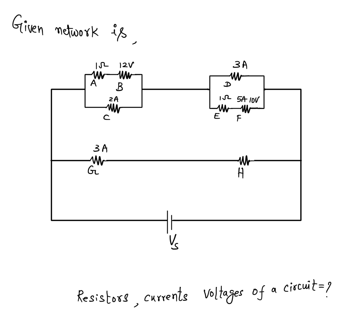
Each of the circuits below consists of a battery and several resistors. Several of the voltages, currents, and resistances are indicated. Use both of Kirchoff's Laws and Ohm's Law to determine as many of the other voltages, currents, and resistances as possible.

Transcribed Image Text:The image displays an electrical circuit diagram featuring a network of resistors, voltage sources, and current measurements. Here is a detailed description:
**Circuit Components:**
1. **Nodes:**
- A, B, C, D, E, F, G, H — Points where components are connected.
2. **Resistors:**
- The circuit includes resistors with unspecified resistance values.
3. **Voltage Sources:**
- 12V source connected between nodes B and D.
4. **Current Measurements:**
- 2A passing through a resistor connected between nodes B and C.
- 5A with a 10V drop connected between nodes E and F.
- 3A current passing through a resistor in the section from node G to H.
**Circuit Description:**
- The circuit predominantly features series and parallel components.
- Starting from node A, a 12V source is connected across a 1Ω resistor extending to node B.
- From node B, a parallel branch includes a resistor with 2A flowing to node C, while another branch runs parallel towards node D through another unspecified resistor.
- The connection from node C towards node E includes another series of resistive elements.
- Between nodes E and F, there's a marked resistor with a current of 5A and a voltage drop of 10V.
- Following the path, the circuit extends vertically from node G to node H with a 3A current through a further unspecified resistor.
This diagram serves as an illustration for understanding the distribution of voltage and current in different segments of an electrical network, beneficial for learning about circuits in physics or electrical engineering studies.
Expert Solution
Step 1: We need to determine resistors , voltages and currents of a circuit

Step by step
Solved in 3 steps with 3 images

Knowledge Booster


Learn more about
Need a deep-dive on the concept behind this application? Look no further. Learn more about this topic, electrical-engineering and related others by exploring similar questions and additional content below.Recommended textbooks for you
Introductory Circuit Analysis (13th Edition)
Electrical Engineering
ISBN:
9780133923605
Author:
Robert L. Boylestad
Publisher:
PEARSON

Delmar's Standard Textbook Of Electricity
Electrical Engineering
ISBN:
9781337900348
Author:
Stephen L. Herman
Publisher:
Cengage Learning

Programmable Logic Controllers
Electrical Engineering
ISBN:
9780073373843
Author:
Frank D. Petruzella
Publisher:
McGraw-Hill Education
Introductory Circuit Analysis (13th Edition)
Electrical Engineering
ISBN:
9780133923605
Author:
Robert L. Boylestad
Publisher:
PEARSON
Delmar's Standard Textbook Of Electricity
Electrical Engineering
ISBN:
9781337900348
Author:
Stephen L. Herman
Publisher:
Cengage Learning
Programmable Logic Controllers
Electrical Engineering
ISBN:
9780073373843
Author:
Frank D. Petruzella
Publisher:
McGraw-Hill Education

Fundamentals of Electric Circuits
Electrical Engineering
ISBN:
9780078028229
Author:
Charles K Alexander, Matthew Sadiku
Publisher:
McGraw-Hill Education

Electric Circuits. (11th Edition)
Electrical Engineering
ISBN:
9780134746968
Author:
James W. Nilsson, Susan Riedel
Publisher:
PEARSON

Engineering Electromagnetics
Electrical Engineering
ISBN:
9780078028151
Author:
Hayt, William H. (william Hart), Jr, BUCK, John A.
Publisher:
Mcgraw-hill Education,