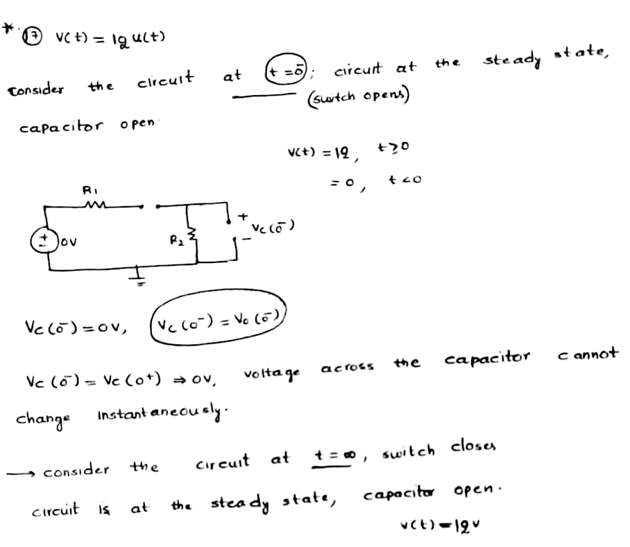
17. The step response of v,(t) of an RC circuit in the Figure 16 below, given that v = 12V, R, = 60, R2 = 302, and C = 1F, is R1 R2 (a) 10cxp(- 5t) V (b) 10(1 – exp(- 5t) V c) 10exp(- 0.2t) V (d) 10{1- exp(- 0.2t)} V
17. The step response of v,(t) of an RC circuit in the Figure 16 below, given that v = 12V, R, = 60, R2 = 302, and C = 1F, is R1 R2 (a) 10cxp(- 5t) V (b) 10(1 – exp(- 5t) V c) 10exp(- 0.2t) V (d) 10{1- exp(- 0.2t)} V

Introductory Circuit Analysis (13th Edition)
13th Edition
ISBN:9780133923605
Author:Robert L. Boylestad
Publisher:Robert L. Boylestad
Chapter1: Introduction
Section: Chapter Questions
Problem 1P: Visit your local library (at school or home) and describe the extent to which it provides literature...

Related questions
Question

Transcribed Image Text:**Problem Statement:**
17. The step response of \( v_o(t) \) of an RC circuit in the Figure 16 below, given that \( v = 12V, R_1 = 6\Omega, R_2 = 30\Omega, \) and \( C = 1F, \) is
**Circuit Diagram Description:**
- The circuit consists of a voltage source \( v \) with a value of 12V.
- A resistor \( R_1 \) with a resistance of 6Ω is connected in series with the voltage source.
- A switch is placed after \( R_1 \), in parallel with a resistor \( R_2 \) and a capacitor \( C \).
- \( R_2 \) has a resistance of 30Ω and is in parallel with a capacitor \( C \) with a capacitance of 1F.
**Question Options:**
(a) \( 10 \exp(-5t) \) V
(b) \( 10(1 - \exp(-5t)) \) V
(c) \( 10 \exp(-0.2t) \) V
(d) \( 10(1 - \exp(-0.2t)) \) V
**Graph/Diagram Explanation:**
There is a diagram illustrating the RC circuit with the aforementioned components and their connections. The positive terminal of the capacitor is also indicated as \( v_o \), representing the output voltage.
Expert Solution
Step 1

Step by step
Solved in 4 steps with 4 images

Recommended textbooks for you
Introductory Circuit Analysis (13th Edition)
Electrical Engineering
ISBN:
9780133923605
Author:
Robert L. Boylestad
Publisher:
PEARSON

Delmar's Standard Textbook Of Electricity
Electrical Engineering
ISBN:
9781337900348
Author:
Stephen L. Herman
Publisher:
Cengage Learning

Programmable Logic Controllers
Electrical Engineering
ISBN:
9780073373843
Author:
Frank D. Petruzella
Publisher:
McGraw-Hill Education
Introductory Circuit Analysis (13th Edition)
Electrical Engineering
ISBN:
9780133923605
Author:
Robert L. Boylestad
Publisher:
PEARSON
Delmar's Standard Textbook Of Electricity
Electrical Engineering
ISBN:
9781337900348
Author:
Stephen L. Herman
Publisher:
Cengage Learning
Programmable Logic Controllers
Electrical Engineering
ISBN:
9780073373843
Author:
Frank D. Petruzella
Publisher:
McGraw-Hill Education

Fundamentals of Electric Circuits
Electrical Engineering
ISBN:
9780078028229
Author:
Charles K Alexander, Matthew Sadiku
Publisher:
McGraw-Hill Education

Electric Circuits. (11th Edition)
Electrical Engineering
ISBN:
9780134746968
Author:
James W. Nilsson, Susan Riedel
Publisher:
PEARSON

Engineering Electromagnetics
Electrical Engineering
ISBN:
9780078028151
Author:
Hayt, William H. (william Hart), Jr, BUCK, John A.
Publisher:
Mcgraw-hill Education,