1 Introduction 2 Voltage And Current 3 Resistance 4 Ohm’s Law, Power, And Energy 5 Series Dc Circuits 6 Parallel Dc Circuits 7 Series-parallel Circuits 8 Methods Of Analysis And Selected Topics (dc) 9 Network Theorems 10 Capacitors 11 Inductors 12 Magnetic Circuits 13 Sinusoidal Alternating Waveforms 14 The Basic Elements And Phasors 15 Series Ac Circuits 16 Parallel Ac Circuits 17 Series-parallel Ac Networks 18 Methods Of Analysis And Selected Topics (ac) 19 Network Theorems (ac) 20 Power (ac) 21 Resonance 22 Decibels, Filters, And Bode Plots 23 Transformers 24 Polyphase Systems 25 Pulse Waveforms And The R-c Response 26 Nonsinusoidal Circuits Chapter1: Introduction
Chapter Questions Section: Chapter Questions
Problem 1P: Visit your local library (at school or home) and describe the extent to which it provides literature... Problem 2P: Choose an area of particular interest in this field and write a very brief report on the history of... Problem 3P: Choose an individual of particular importance in this field and write a very brief review of his or... Problem 4P: In a recent Tour de France time trial, a participant traveled 30.5 mi in a time trial in 1 h, 10... Problem 5P: Outside the United States speed is measured in Kilometers per hour (km/h) rather than miles per hour... Problem 6P Problem 7P: A pitcher has the ability to throw a baseball at 95 mph. How fast is the speed in ft/s? How long... Problem 8P: Are there any relative advantages associated with the metric system compared to the English system... Problem 9P: Which of the four systems of units appearing in Table 1.1 has the smallest units for length, mass,... Problem 10P: Which system of Table 1.1 is closest in definition to the SI system? How are the two systems... Problem 11P: What is room temperature (68F) in the MKS, CGS, and SI systems? Problem 12P: How many foot-pounds of energy are associated with 1000 J? Problem 13P: In Europe the height of a man or woman is measured in centimeters and his or her weight in... Problem 14P: Throughout the world, the majority of countries use the centigrade scale rather than the Fahrenheit... Problem 15P: Write the following numbers to tenths-place accuracy. 14.6026 056.0420 1,046.06 1/6 Problem 16P: Repeat Problem 15 using hundredths-place accuracy. Problem 17P: Repeat Problem 15 using thousandths-place accuracy. Problem 18P: Express the following numbers as powers of ten to hundredths-place accuracy: 10,000 1,000,000 1000... Problem 19P: Using only those powers of ten listed in Table 1.2 express the following numbers in what seems to... Problem 20P: Perform the following operations to hundredths-place accuracy: 4200+48,000 9104+3.6105 0.51036105... Problem 21P Problem 22P: Perform the following operations to hundredths—place accuracy: (50,000)(0.002) 22000.002... Problem 23P: Perform the following operations: 10010,000 0.0101000 10,0000.001 0.0000001100 10380.000100... Problem 24P: Perform the following operations to hundredths-place accuracy: 20000.00008 0.0044106 0.0002200.00005... Problem 25P Problem 26P: Perform the following operations to hundredths-place accuracy: (200)2 (5103)3 (0.004)(3103)2... Problem 27P: Perform the following operations to hundredths-place accuracy: (300)2(100)3104 [ (40,000)2 ][ (20)3... Problem 28P: Write the following numbers in scientific and engineering notation to hundredths place: 20.46 50,420... Problem 29P: Write the following numbers in scientific and engineering notation to tenths place: 5102 0.4510+2... Problem 30P: Perform the following operations and leave the answer in engineering notation: (6103)(4104)=... Problem 31P: Fill in the blanks of the following conversions: 6104= 106 0.4103= 106 50105= 103= 106 = 109 12107=... Problem 32P: Perform the following conversions: 0.05 s to milliseconds 2000s to milliseconds 0.04 ms to... Problem 33P: Perform the following conversions to tenths—place accuracy: 1.5 min to seconds 210-2h to seconds... Problem 34P: Perform the following metric conversions to tenths-place accuracy: 12103m 80 mm to centimeters 60 cm... Problem 35P: Perform the following conversions between systems to hundredths-place accuracy: 100 in. to meters 4... Problem 36P: What is a mile in feet, yards, meters, and kilometers? Problem 37P: Convert 60 mph to meters per second. Problem 38P: How long would it take a runner to complete a 10-km race if a pace of 6.5 min/mi were maintained? Problem 39P: Quarters are about 1 in. in diameter. How many would be required to stretch from one end of a... Problem 40P: Compare the total time required to drive a long, tiring day of 500 m at an average speed of 60mph... Problem 41P: Find the distance in meters that a mass traveling at 600 cm/s will cover in 0.016 h. Problem 42P: Each spring there is a race up 86 floors of the 102-story Empire State Building in New York City.... Problem 43P: The record for the race in Problem 42 is 10.22 min. What was the racers speed in min/mi for the... Problem 44P Problem 45P: Using Appendix A, determine the number of Btu in 5 J of energy. cubic meters in 24 oz of a liquid.... Problem 46P: 6(42+8)= Problem 47P Problem 48P: 52+(23)2= Problem 49P: cos21.87= Problem 50P: tan134= Problem 51P: 40062+105= Problem 52P: 8.21030.04103 (in engineering notation) = Problem 53P: (0.06105)(20103)(0.01)2 (engineering notation) = Problem 54P: 41042103+400105+12106 (in engineering notation) = Problem 55P: Investigate the availability of computer courses and computer time in your curriculum. Which... Problem 56P Problem 1P: Visit your local library (at school or home) and describe the extent to which it provides literature...
Related questions
Concept explainers
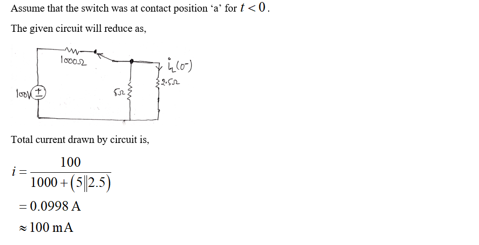
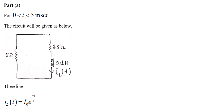
Consider the circuit of Figure P5.49, and assumemechanical switching action requires 5 ms.L (t) for 0 < t < 5 ms
Transcribed Image Text: 1,000 2
ww-
iz(f)
t= 0
2.5 2
100 V
50
0.1 H
(+)
Branch of science that deals with the stationary and moving bodies under the influence of forces.
Expert Solution
Step by step
Solved in 3 steps with 7 images
UNLOCK THE REST


