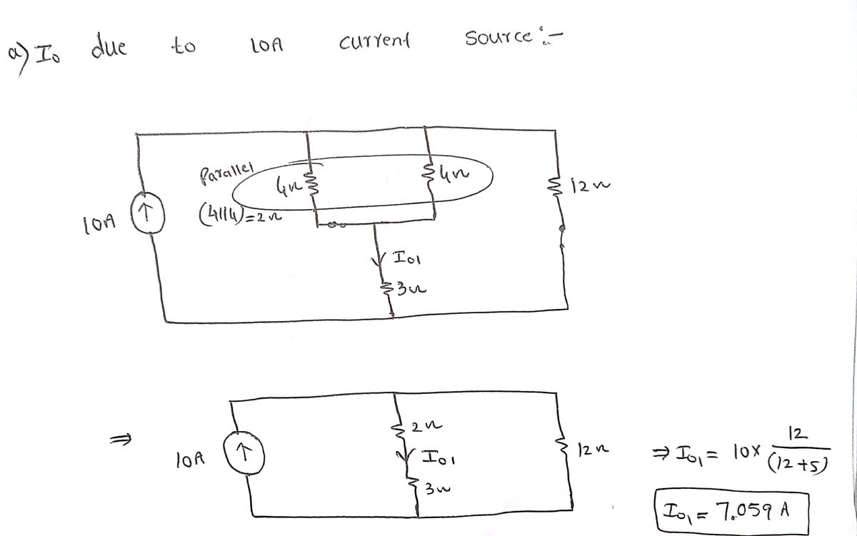
10 A 4ΩΣ 48 V (+ ww R Io 4Ω ww 80 V(+ +1 Select the contribution each source makes to Io (in Amps) if it appears in the list below. ** Select only partial solutions; not the final solution ** 12 Ω
10 A 4ΩΣ 48 V (+ ww R Io 4Ω ww 80 V(+ +1 Select the contribution each source makes to Io (in Amps) if it appears in the list below. ** Select only partial solutions; not the final solution ** 12 Ω

Introductory Circuit Analysis (13th Edition)
13th Edition
ISBN:9780133923605
Author:Robert L. Boylestad
Publisher:Robert L. Boylestad
Chapter1: Introduction
Section: Chapter Questions
Problem 1P: Visit your local library (at school or home) and describe the extent to which it provides literature...

Related questions

Question
The superposition technique can be described as a multi-step process of calculating the contributions of each source. Then, all of the individual solutions are combined to yield the final solution.
If R=3Ω and superposition is used to compute the current I_0, what are the individual solutions for I_0 (in Amps)?
Please answer in typing format please ASAP for the like

Transcribed Image Text:The image displays a list of numbers, each accompanied by a checkbox. The numbers are arranged in the following sequence:
- 7.059
- -1.412
- 4.706
- 3.294
- -3.294
- 5.882
- -5.882
- 4.059
- -4.059
- 9.235
- -9.235
- -7.059
- 1.412
- -4.706
There are no graphs or diagrams present in the image. Each number is a decimal, and the sequence includes both positive and negative values. The presence of checkboxes suggests that these numbers may be part of a selection or sorting activity.

Transcribed Image Text:### Circuit Diagram
This is an illustration of an electrical circuit containing the following components:
- **Current Source**: A 10 A current source is placed on the left side, producing an upward-directed current.
- **Resistors**:
- Two resistors, each with a resistance of 4 Ω, are positioned on the top branches of the circuit.
- One resistor with a resistance of 12 Ω is placed on the rightmost part of the circuit.
- **Voltage Sources**:
- A 48 V voltage source is connected in series between the 4 Ω resistors.
- An 80 V voltage source is placed in series beneath the 12 Ω resistor, oriented with the negative terminal facing upwards.
- **Resistor (R)**: An unspecified resistor, R, is oriented vertically in the lower middle section of the circuit.
- **Output Current (Iₒ)**: The current Iₒ flows through the resistor R.
### Instruction
The task is to determine the contribution each source makes to the output current \( I_0 \) (in Amps). Note that the instruction specifically asks to identify only partial solutions from a given list, not the final solution.
### Note
**Select only partial solutions; not the final solution.**
Expert Solution
Step 1: Mesh analysis

Trending now
This is a popular solution!

Step by step
Solved in 4 steps with 3 images

Knowledge Booster


Learn more about
Need a deep-dive on the concept behind this application? Look no further. Learn more about this topic, electrical-engineering and related others by exploring similar questions and additional content below.Recommended textbooks for you
Introductory Circuit Analysis (13th Edition)
Electrical Engineering
ISBN:
9780133923605
Author:
Robert L. Boylestad
Publisher:
PEARSON

Delmar's Standard Textbook Of Electricity
Electrical Engineering
ISBN:
9781337900348
Author:
Stephen L. Herman
Publisher:
Cengage Learning

Programmable Logic Controllers
Electrical Engineering
ISBN:
9780073373843
Author:
Frank D. Petruzella
Publisher:
McGraw-Hill Education
Introductory Circuit Analysis (13th Edition)
Electrical Engineering
ISBN:
9780133923605
Author:
Robert L. Boylestad
Publisher:
PEARSON
Delmar's Standard Textbook Of Electricity
Electrical Engineering
ISBN:
9781337900348
Author:
Stephen L. Herman
Publisher:
Cengage Learning
Programmable Logic Controllers
Electrical Engineering
ISBN:
9780073373843
Author:
Frank D. Petruzella
Publisher:
McGraw-Hill Education

Fundamentals of Electric Circuits
Electrical Engineering
ISBN:
9780078028229
Author:
Charles K Alexander, Matthew Sadiku
Publisher:
McGraw-Hill Education

Electric Circuits. (11th Edition)
Electrical Engineering
ISBN:
9780134746968
Author:
James W. Nilsson, Susan Riedel
Publisher:
PEARSON

Engineering Electromagnetics
Electrical Engineering
ISBN:
9780078028151
Author:
Hayt, William H. (william Hart), Jr, BUCK, John A.
Publisher:
Mcgraw-hill Education,