1. Using the circuit of Figure 2.1 with RI -1 k, R2 =2,2 k, R3 the theoretical current and record it in Tahle 2,1, Construet the circuit, Set the 3.6 k, and E -9 volls, detyrmine DMM to read DC current and insert it in the cireuit at point A. Remerber, ammeters goin-line and require the circuit to be opened for proper measurement. The red lead should be placed closer to the positive source terminal. Record this current in Table 2.1. Repeat the current measurements at points B and C. 2. Using the theoretical current found in Step 1, apply Ohm's law to determine the expected voltage drops across RI, R2, and R3. Record these values in the Theory column of Table 2.2.
1. Using the circuit of Figure 2.1 with RI -1 k, R2 =2,2 k, R3 the theoretical current and record it in Tahle 2,1, Construet the circuit, Set the 3.6 k, and E -9 volls, detyrmine DMM to read DC current and insert it in the cireuit at point A. Remerber, ammeters goin-line and require the circuit to be opened for proper measurement. The red lead should be placed closer to the positive source terminal. Record this current in Table 2.1. Repeat the current measurements at points B and C. 2. Using the theoretical current found in Step 1, apply Ohm's law to determine the expected voltage drops across RI, R2, and R3. Record these values in the Theory column of Table 2.2.

Introductory Circuit Analysis (13th Edition)
13th Edition
ISBN:9780133923605
Author:Robert L. Boylestad
Publisher:Robert L. Boylestad
Chapter1: Introduction
Section: Chapter Questions
Problem 1P: Visit your local library (at school or home) and describe the extent to which it provides literature...

Related questions
Question
100%
Help please

Transcribed Image Text:Part A: Series Circuits
Objective
The focus of this exercise is an examination of basic series/parallel DC circuits with resistors. A key
element is KirchhofTs voltuve law whichı states that the sum of voitage rises around a loop inust equal the
sum of the voltage drops. The voltage divider rule will also be investigated.
Theory Overview
A series circuit is defined by a single loop in which all components are arranged in daisy-chain fashion.
The current is the same at all points in the loop and may be found by dividing the total voltage source by
the total resistance. The voltage drops across any resistor may then he found by multiplying that current
by the resistor value, Consequently, the voltage drops in a scries circuit are directly proportional to the
resistance. An alternate technique to find the voltage is the voltage divider rule. This states that the
voltage across any resistor (or combination of resistors) is equal to the total voltage source times the ratio
of the resistance of interest to the total resistance.
Equipment
(1) Adjustable DC power supply
(1) Digital multimeter
(1) 560 2
(1) I k2
(1) 1.5 k2
(1) 2.2 k2
(1) 3.6 k2
(1) 4,7 ko
A
В
Schematics
R1
R3
Figure 2.1
Laboratory Manual for Circuits Lab

Transcribed Image Text:Figure 2.4
Laboratory Manual for Circuits Lab
R1
R2
Figure 2.2
Procedure
1.
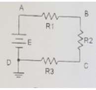
Using the circuit of Figure 2.1 with R1 =1 k, R2 =2,2 k. R3 3.6 k, and E =9 volis, determine
the theoretical current and record it in Tahle 2.1, Construet the circuit. Set the DMM to read DC
current and insert it in the circuit at point A. Remerrber, ammeters goin-line and require the
circuit to be opened for proper measurement. The red lead should be placed closer to the positive
source terrninal. Record this current in Table 2.1. Repeat the current imeasurements at points B and
C.
2. Using the theoretical curent found in Step 1, apply Ohm's law to determine the expected voltage
drops across RI, R2, and R3. Record these values in the Theory column of Table 2.2.
3.
Set the DMM to measure DC voltage. Remember, unlike current. voltage is measured across
components. Place the DMM probes across R1 and mcasure its voltage. Again, red lead should be
placed closer to the positive source lerminal. Record this value in Table 2.2. Repeat this process for
the voltages across R2 and R3. Determine the percent deviation between theoretical and measured
for cach of the three resistor voltages and record these in the final column of Table 2.2.
Expert Solution
Step 1
Note: Here we have solved only theory part of the questions.
For remaining parts, actual experiment and simulation need to perform.
For first 2 questions, given circuit is
R1=1K ohm, R2=2.2 K ohm and R3=3.6 K ohm
E=9 V

Step by step
Solved in 3 steps with 5 images

Knowledge Booster


Learn more about
Need a deep-dive on the concept behind this application? Look no further. Learn more about this topic, electrical-engineering and related others by exploring similar questions and additional content below.Recommended textbooks for you
Introductory Circuit Analysis (13th Edition)
Electrical Engineering
ISBN:
9780133923605
Author:
Robert L. Boylestad
Publisher:
PEARSON

Delmar's Standard Textbook Of Electricity
Electrical Engineering
ISBN:
9781337900348
Author:
Stephen L. Herman
Publisher:
Cengage Learning

Programmable Logic Controllers
Electrical Engineering
ISBN:
9780073373843
Author:
Frank D. Petruzella
Publisher:
McGraw-Hill Education
Introductory Circuit Analysis (13th Edition)
Electrical Engineering
ISBN:
9780133923605
Author:
Robert L. Boylestad
Publisher:
PEARSON
Delmar's Standard Textbook Of Electricity
Electrical Engineering
ISBN:
9781337900348
Author:
Stephen L. Herman
Publisher:
Cengage Learning
Programmable Logic Controllers
Electrical Engineering
ISBN:
9780073373843
Author:
Frank D. Petruzella
Publisher:
McGraw-Hill Education

Fundamentals of Electric Circuits
Electrical Engineering
ISBN:
9780078028229
Author:
Charles K Alexander, Matthew Sadiku
Publisher:
McGraw-Hill Education

Electric Circuits. (11th Edition)
Electrical Engineering
ISBN:
9780134746968
Author:
James W. Nilsson, Susan Riedel
Publisher:
PEARSON

Engineering Electromagnetics
Electrical Engineering
ISBN:
9780078028151
Author:
Hayt, William H. (william Hart), Jr, BUCK, John A.
Publisher:
Mcgraw-hill Education,