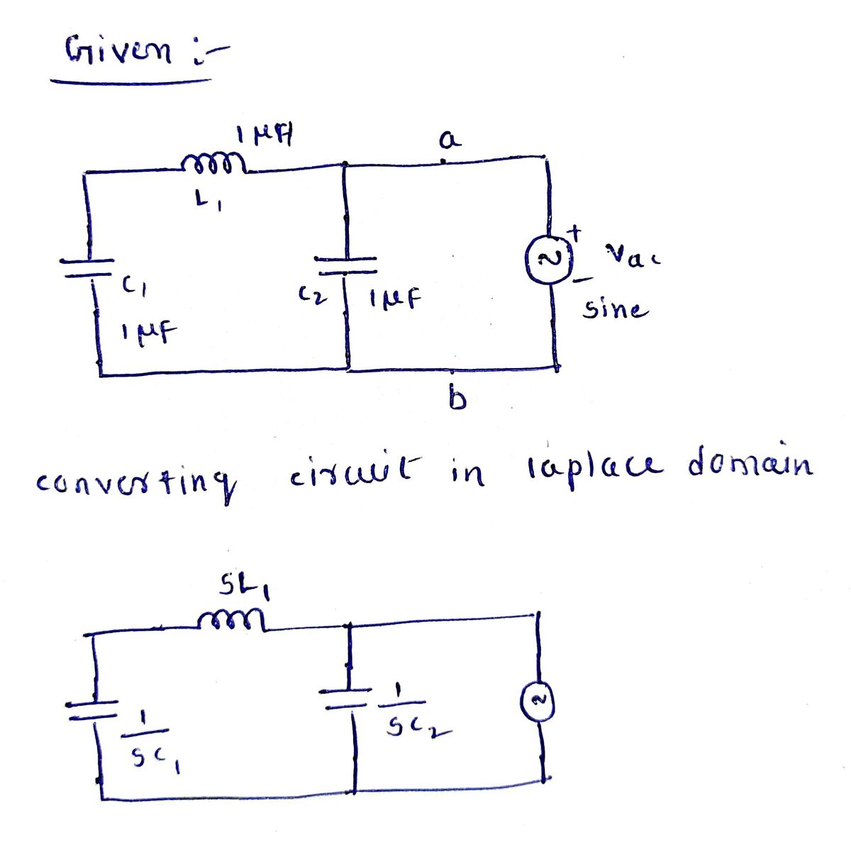
1. Consider the two circuits below being driven by an AC source Vac. What is the impedance between terminals a and b as the frequency goes to zero? What is the impedance as the frequency become extremely high? ell L1 1 ΜΗ C1 1 µF C2 1 µF b t Vac sine C3 L2 1 μF 1 ΜΗ L3 1 ΜΗ Vac sine
1. Consider the two circuits below being driven by an AC source Vac. What is the impedance between terminals a and b as the frequency goes to zero? What is the impedance as the frequency become extremely high? ell L1 1 ΜΗ C1 1 µF C2 1 µF b t Vac sine C3 L2 1 μF 1 ΜΗ L3 1 ΜΗ Vac sine

Introductory Circuit Analysis (13th Edition)
13th Edition
ISBN:9780133923605
Author:Robert L. Boylestad
Publisher:Robert L. Boylestad
Chapter1: Introduction
Section: Chapter Questions
Problem 1P: Visit your local library (at school or home) and describe the extent to which it provides literature...

Related questions
Question

Transcribed Image Text:**Problem Statement:**
1. Consider the two circuits below being driven by an AC source \(V_{ac}\). What is the impedance between terminals a and b as the frequency goes to zero? What is the impedance as the frequency becomes extremely high?
---
**Diagram Explanation:**
The image contains two circuits, each driven by an AC voltage source labeled \(V_{ac}\) with a sine wave symbol.
- **First Circuit:**
- Components:
- Inductor \(L1\) with an inductance of 1 μH.
- Capacitor \(C1\) with a capacitance of 1 μF.
- Capacitor \(C2\) with a capacitance of 1 μF.
- Configuration:
- \(L1\) and \(C1\) are in parallel.
- The parallel combination is in series with \(C2\).
- Terminals a and b are connected across this series combination.
- **Second Circuit:**
- Components:
- Capacitor \(C3\) with a capacitance of 1 μF.
- Inductor \(L2\) with an inductance of 1 μH.
- Inductor \(L3\) with an inductance of 1 μH.
- Configuration:
- \(C3\) is in series with \(L2\).
- \(L2\) is in parallel with \(L3\).
- Terminals a and b are connected across this entire combination.
---
**Analysis Task:**
- **Low Frequency Analysis (\(f \to 0\)):**
- Inductors (\(L\)) act as short circuits.
- Capacitors (\(C\)) act as open circuits.
- **High Frequency Analysis (\(f \to \infty\)):**
- Inductors (\(L\)) act as open circuits.
- Capacitors (\(C\)) act as short circuits.
Expert Solution
Step 1

Step by step
Solved in 2 steps with 2 images

Knowledge Booster


Learn more about
Need a deep-dive on the concept behind this application? Look no further. Learn more about this topic, electrical-engineering and related others by exploring similar questions and additional content below.Recommended textbooks for you
Introductory Circuit Analysis (13th Edition)
Electrical Engineering
ISBN:
9780133923605
Author:
Robert L. Boylestad
Publisher:
PEARSON

Delmar's Standard Textbook Of Electricity
Electrical Engineering
ISBN:
9781337900348
Author:
Stephen L. Herman
Publisher:
Cengage Learning

Programmable Logic Controllers
Electrical Engineering
ISBN:
9780073373843
Author:
Frank D. Petruzella
Publisher:
McGraw-Hill Education
Introductory Circuit Analysis (13th Edition)
Electrical Engineering
ISBN:
9780133923605
Author:
Robert L. Boylestad
Publisher:
PEARSON
Delmar's Standard Textbook Of Electricity
Electrical Engineering
ISBN:
9781337900348
Author:
Stephen L. Herman
Publisher:
Cengage Learning
Programmable Logic Controllers
Electrical Engineering
ISBN:
9780073373843
Author:
Frank D. Petruzella
Publisher:
McGraw-Hill Education

Fundamentals of Electric Circuits
Electrical Engineering
ISBN:
9780078028229
Author:
Charles K Alexander, Matthew Sadiku
Publisher:
McGraw-Hill Education

Electric Circuits. (11th Edition)
Electrical Engineering
ISBN:
9780134746968
Author:
James W. Nilsson, Susan Riedel
Publisher:
PEARSON

Engineering Electromagnetics
Electrical Engineering
ISBN:
9780078028151
Author:
Hayt, William H. (william Hart), Jr, BUCK, John A.
Publisher:
Mcgraw-hill Education,