1 V + Vx 202 ww Find the power received by each of the four elements. 1Ω 2Vx
1 V + Vx 202 ww Find the power received by each of the four elements. 1Ω 2Vx

Introductory Circuit Analysis (13th Edition)
13th Edition
ISBN:9780133923605
Author:Robert L. Boylestad
Publisher:Robert L. Boylestad
Chapter1: Introduction
Section: Chapter Questions
Problem 1P: Visit your local library (at school or home) and describe the extent to which it provides literature...

Related questions

Question
100%
Simple circuits techniques

Transcribed Image Text:**Educational Content: Analyzing a Circuit**
**Task:**
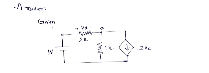
Find the power received by each of the four elements in the given circuit diagram.
**Diagram Explanation:**
The circuit consists of the following components:
1. **Voltage Source**:
- A 1V voltage source on the left side of the circuit.
2. **Resistors**:
- A 2Ω resistor in series with the voltage source.
- A 1Ω resistor in parallel with the other components on the right side.
3. **Voltage-Controlled Current Source**:
- Labeled as 2Vx, positioned vertically, indicating the current direction is downward.
**Analysis Steps:**
1. **Identify Unknowns**:
- The voltage across the 2Ω resistor is labeled as Vx.
- The current source is labeled with 2Vx, meaning the current depends on Vx.
2. **Calculate Vx**:
- Use Ohm's law (V = IR) and Kirchhoff’s laws to find the voltage Vx across the 2Ω resistor.
3. **Determine the Currents**:
- Calculate the currents flowing through each resistor and the current source using the values found.
4. **Calculate Power**:
- Use the formula P = IV for each element, where P is power, I is current, and V is voltage.
5. **Verify Power Balance**:
- Ensure the total power delivered equals the total power absorbed, according to the conservation of energy.
By solving these steps, you can find the power received by each element in the circuit to understand the energy distribution within this configuration.
Expert Solution
Step 1

Step by step
Solved in 2 steps with 2 images

Knowledge Booster


Learn more about
Need a deep-dive on the concept behind this application? Look no further. Learn more about this topic, electrical-engineering and related others by exploring similar questions and additional content below.Recommended textbooks for you
Introductory Circuit Analysis (13th Edition)
Electrical Engineering
ISBN:
9780133923605
Author:
Robert L. Boylestad
Publisher:
PEARSON

Delmar's Standard Textbook Of Electricity
Electrical Engineering
ISBN:
9781337900348
Author:
Stephen L. Herman
Publisher:
Cengage Learning

Programmable Logic Controllers
Electrical Engineering
ISBN:
9780073373843
Author:
Frank D. Petruzella
Publisher:
McGraw-Hill Education
Introductory Circuit Analysis (13th Edition)
Electrical Engineering
ISBN:
9780133923605
Author:
Robert L. Boylestad
Publisher:
PEARSON
Delmar's Standard Textbook Of Electricity
Electrical Engineering
ISBN:
9781337900348
Author:
Stephen L. Herman
Publisher:
Cengage Learning
Programmable Logic Controllers
Electrical Engineering
ISBN:
9780073373843
Author:
Frank D. Petruzella
Publisher:
McGraw-Hill Education

Fundamentals of Electric Circuits
Electrical Engineering
ISBN:
9780078028229
Author:
Charles K Alexander, Matthew Sadiku
Publisher:
McGraw-Hill Education

Electric Circuits. (11th Edition)
Electrical Engineering
ISBN:
9780134746968
Author:
James W. Nilsson, Susan Riedel
Publisher:
PEARSON

Engineering Electromagnetics
Electrical Engineering
ISBN:
9780078028151
Author:
Hayt, William H. (william Hart), Jr, BUCK, John A.
Publisher:
Mcgraw-hill Education,