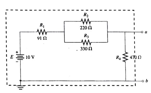
. E HIF 10 V R₁ Μ 91Ω R₂ Μ 220 Ω R3 Μ 330 Ω R, Σ 470 Ω | ο α ob R₁ R₂ R R
. E HIF 10 V R₁ Μ 91Ω R₂ Μ 220 Ω R3 Μ 330 Ω R, Σ 470 Ω | ο α ob R₁ R₂ R R
Introductory Circuit Analysis (13th Edition)
13th Edition
ISBN:9780133923605
Author:Robert L. Boylestad
Publisher:Robert L. Boylestad
Chapter1: Introduction
Section: Chapter Questions
Problem 1P: Visit your local library (at school or home) and describe the extent to which it provides literature...
Related questions
Question
100%
i need ETH AND RTH calculation

Transcribed Image Text:E
FIG. 12.8
(a) Construct the network of Fig. 12.8. Insert the measured value of each resistor.
높
10 V
R₁
www
9122
R₂
220 Ω
R3
ww
330 Ω
R₁
1
I
470 Ω
1
a
b
R1 measured =
R2 measured =
R3 measured
R4 measured =
=

Transcribed Image Text:(b) The Thevenin equivalent circuit will now be determined for the network to the
left of the terminals a-b without disturbing the structure of the network. All the measurements
will be made at the terminals a-b.
ETh
ab
Determine Eh by turning on the supply and measuring the open-circuit voltage Va
Record the reading in Table 12.6.
RTh
FIG. 12.9
TABLE 12.6
Introduce the 1-k potentiometer to the network of Fig. 12.8, as shown in Fig. 12.9.
ETh
RTH
ao
Measured
Calculation:
bo
Turn on the supply and adjust the potentiometer until the voltage V₁ is ETH/2, a con-
dition that must exist if R₁ = Rh. Then turn off the supply and remove the potentiometer from
the network without disturbing the position of the wiper arm. Measure the resistance between the
two terminals connected to a-b and record as RT in Table 12.6, first column.
1-kΩ potentiometer
www
RL
Calculated
(c) Now we need to check our measured results against a theoretical solution.
Calculate RT and Erh for the network to the left of terminals a-b of Fig. 12.8 and record in the
second column of Table 12.6. Use measured resistor values.
How do the calculated and measured values compare?
(d) Now plot P, and V₁ versus R, to confirm once more that the conditions
imum power transfer to a load are that R₁ RT and V₁ = ETth/2.
Leave the potentiometer as connected in Fig. 12.9 and measure V₁ for all th
of R₁ appearing in Table 12.7. Then calculate the resulting power to the load and comp
table. Finally, plot both P, and V, versus R₁ on Graphs 12.2 and 12.3, respectively.
TABLE 12.7
Ri
ΟΩ
25 Ω
50 Ω
100 Ω
150 Ω
200 Ω
250 Ω
300 Ω
350 Ω
400 Ω
450 Ω
500 Ω
V₁ (measured)
OV
PL
VZ/R, (calculated)
0 mW
*Be sure to remove the potentiometer from the network when setting each value of R₁.
At the very least, disconnect one side of the potentiometer when making the setting.
Expert Solution
Step 1: Summarize the details given:
Given Data:
A DC resistive circuit of,

To Find:
Thevenin's Equivalent Voltage and Resistance.
Step by step
Solved in 3 steps with 7 images

Knowledge Booster
Learn more about
Need a deep-dive on the concept behind this application? Look no further. Learn more about this topic, electrical-engineering and related others by exploring similar questions and additional content below.Recommended textbooks for you

Introductory Circuit Analysis (13th Edition)
Electrical Engineering
ISBN:
9780133923605
Author:
Robert L. Boylestad
Publisher:
PEARSON

Delmar's Standard Textbook Of Electricity
Electrical Engineering
ISBN:
9781337900348
Author:
Stephen L. Herman
Publisher:
Cengage Learning

Programmable Logic Controllers
Electrical Engineering
ISBN:
9780073373843
Author:
Frank D. Petruzella
Publisher:
McGraw-Hill Education

Introductory Circuit Analysis (13th Edition)
Electrical Engineering
ISBN:
9780133923605
Author:
Robert L. Boylestad
Publisher:
PEARSON

Delmar's Standard Textbook Of Electricity
Electrical Engineering
ISBN:
9781337900348
Author:
Stephen L. Herman
Publisher:
Cengage Learning

Programmable Logic Controllers
Electrical Engineering
ISBN:
9780073373843
Author:
Frank D. Petruzella
Publisher:
McGraw-Hill Education

Fundamentals of Electric Circuits
Electrical Engineering
ISBN:
9780078028229
Author:
Charles K Alexander, Matthew Sadiku
Publisher:
McGraw-Hill Education

Electric Circuits. (11th Edition)
Electrical Engineering
ISBN:
9780134746968
Author:
James W. Nilsson, Susan Riedel
Publisher:
PEARSON

Engineering Electromagnetics
Electrical Engineering
ISBN:
9780078028151
Author:
Hayt, William H. (william Hart), Jr, BUCK, John A.
Publisher:
Mcgraw-hill Education,