
Concept explainers
Videos
Determine the moments of inertia and the product of inertia of the L3 × 2 ×
9.71 through 9.74 Using the parallel-axis theorem, determine the product of inertia of the area shown with respect to the centroidal x and y axes.
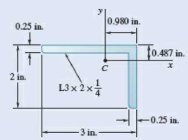
Fig. P9.74
Want to see the full answer?
Check out a sample textbook solution
Chapter 9 Solutions
Vector Mechanics for Engineers: Statics and Dynamics
Additional Engineering Textbook Solutions
Fluid Mechanics: Fundamentals and Applications
Automotive Technology: Principles, Diagnosis, And Service (6th Edition) (halderman Automotive Series)
Database Concepts (8th Edition)
Starting Out with Java: From Control Structures through Objects (7th Edition) (What's New in Computer Science)
Thermodynamics: An Engineering Approach
Elementary Surveying: An Introduction To Geomatics (15th Edition)


- Problem A2 long steel tube has a rectangular cross-section with outer dimensions of 20 x 20 mm and a uniform wall thickness of 2. The tube is twisted along its length with torque, T. The tube material is 1045 CD steel with shear yield strength of S,, =315 MPa. Assume shear modulus, G = 79.3GPa. (a) Estimate the maximum torque that can be applied without yielding (b) Estimate the torque required to produce 5 degrees total angle of twist over the length of the tube. (c) What is the maximum torque that can be applied without yielding, if a solid rectangular shaft with dimensions of 20 x 20 is used? You may use the exact solution.arrow_forwardA simply supported beam is loaded as shown. Considering symmetry, the reactions at supports A and B are R₁ = R₂ = wa 2 Using the singularity method, determine the shear force V along the length of the beam as a function of distance x from the support A. A B Ir. 2a За W C R₁₂ x 2. Using the singularity method, determine the bending M along the length of the beam as a function of distance x, from the support A. 3. Using the singularity method, determine the beam slope and deflection along the length of the beam as a function of the distance x, from the support A. Assume the material modulus of elasticity, E and the moment of inertia of the beam cross-section, I are given.arrow_forwardA steel tube, 2 m long, has a rectangular cross-section with outer dimensions of 20 × 30 mm and a uniform wall thickness of 1 mm. The tube is twisted along its length with torque, T. The tube material is 1018 CD steel with shear yield strength of Ssy =185 MPa. Assume shear modulus, G = 79.3GPa. (a) Estimate the maximum torque that can be applied without yielding.- (b) Estimate the torque required to produce 3 degrees total angle of twist over the length of the tube. (c) What is the maximum torque that can be applied without yielding, if a solid rectangular shaft with dimensions of 20 x 30 mm is used? You may use the exact solution:arrow_forward
- |The typical cruising altitude of a commercial jet airliner is 10,700 m above sea level where the local atmospheric temperature is 219 K, and the pressure is 0.25 bar. The aircraft utilizes a cold air-standard Brayton cycle as shown with a volume flow rate of 1450 m³/s. The compressor pressure ratio is 50, and the maximum cycle temperature is 1700 K. The compressor and turbine isentropic efficiencies are 90%. Neglect kinetic and potential energy effects in this problem. Assume constant specific heats with k=1.4, Ra=0.287 kJ/kg- K, Cp=1.0045 kJ/kg-K, and cv = 0.7175 kJ/kg-K. a) Draw a T-s diagram for this cycle on the diagram provided. b) Fill in the table below with the missing information. T[K] Heat exchanger Heat exchanger State P [bar] 1 0.25 2s 2 3 4s 4 Turbine c) (5pts) Determine the inlet air density in [kg/m³] (at state 1), and the system mass flowrate in [kg/s]. d) (10pts) Determine the net power developed in [MW]. Be sure to draw each component you are analyzing, define the…arrow_forwardOn the axis provide, draw a corresponding T-s diagram for the Brayton cycle shown given the following information: iv. V. vi. Compressor 1 is reversible, but Compressor 2 and the turbine are irreversible. The pressure drops through the regenerator are combustors are negligible. The pressures at state (1) and state (10) are equal to the atmospheric pressure. T 8 Regenerator fmm mmm Qin Combustor Compressor Compressor Turbine W cycle Intercooler mm Courarrow_forwardFor parts a) through e), consider the two power cycles shown in the diagram at the right, Cycle A: 1-2-3-4-1, and Cycle B: 1-2-3-4-1. a) What type of power cycles are shown? b) Which of cycles has a higher efficiency? c) Which of the cycles has a higher work output? d) For either cycle, would increasing the maximum cycle temperature (3) increase or decrease the efficiency? Cycle A: 1-2-3-4-1 3 3 Cycle B: 1-2-3-4-1 1 e) For either cycle, would decreasing the minimum cycle temperature (1) increase or decrease the efficiency? f) On the axis provide, draw a corresponding T-s diagram for the Rankine cycle shown given the following information: i. All turbines and pumps in the system are irreversible. ii. 111. The turbine inlet conditions (states 1 and 2) are superheated, while the 2nd stage turbine outlet is a saturated mixture. The condenser outlet state (4) and the CFWH outlet state (7) are saturated liquid. 2 Steam generator Condenser www Closed feedwater heater (1-y) T Pump Trap 8 (y) Sarrow_forward
- Problem 4 A glass sphere with a 30 mm diameter is pressed against a flat carbon steel plate with a force of 5 N. Assume. For glass: E = 46.2 GPa, -0.245 and for steel E, 207 GPa, (a) Determine the radius of the contact surface. -0.292 (4 (b) Determine the maximum pressure at the contact surface. (4 (c) Calculate the principal stresses d., and a, in the glass sphere at the depth=0.037 mm. (d) Maximum shear stress in the glass sphere at the depth: 0.037 mm. (t (4 (e) Draw the Mohr circles for the stresses and show the point corresponding to the maximum shear stress. (3arrow_forwardSteam is the working fluid in the vapor power cycle with reheat shown in the figure. The mass flow rate is 0.5 kg/s, and the turbines and pump operate isentropically. The temperature at the inlet of both turbine stages (i.e. states 1 and 3) is 400 °C The condenser outlet is saturated liquid. 1. Fill in the table below with the missing information. Reheat section High- pressure turbine State P [bar] h [kJ/kg] s [kJ/kg-K] x [-] Steam generator 1 140 Condenser Pump 2 40 5 3 4 4 5 6 2.Draw a T-s diagram for this cycle on the diagram provided 3. Determine the net power output of this cycle in [kW]. Be sure to draw the component(s) you are analyzing, define the system, and apply conservation of energy in the space below. 4.Determine the total heat transferred into the system in [kW]. Be sure to draw the component you are analyzing, define the system, and apply conservation of energy in the space bel 5.Determine the cycle efficiency. Low-pressure turbinearrow_forwardCalculate the moment of F about axis AB. Express the moment as a Cartesian vector, and then state its magnitude. The radii of the curved sections are all 0.5 m. F acts on the bottom center of the hook, and the hook lies in the yz plane.arrow_forward
- Determine the moment created by the force FAB about the point E. Assume FAB = 800 lbs. Express your answer as a Cartesian vector (ME) and state the magnitude of the moment.arrow_forwardDetermine the couple moment acting on the beam. Express it as a Cartesian vector.arrow_forwardDetermine Cartesian vector expressions for reaction forces at A and B i.e. determine FA and FB.arrow_forward
 Elements Of ElectromagneticsMechanical EngineeringISBN:9780190698614Author:Sadiku, Matthew N. O.Publisher:Oxford University Press
 Mechanics of Materials (10th Edition)Mechanical EngineeringISBN:9780134319650Author:Russell C. HibbelerPublisher:PEARSON
 Thermodynamics: An Engineering ApproachMechanical EngineeringISBN:9781259822674Author:Yunus A. Cengel Dr., Michael A. BolesPublisher:McGraw-Hill Education
 Control Systems EngineeringMechanical EngineeringISBN:9781118170519Author:Norman S. NisePublisher:WILEY
 Mechanics of Materials (MindTap Course List)Mechanical EngineeringISBN:9781337093347Author:Barry J. Goodno, James M. GerePublisher:Cengage Learning
 Engineering Mechanics: StaticsMechanical EngineeringISBN:9781118807330Author:James L. Meriam, L. G. Kraige, J. N. BoltonPublisher:WILEY