
Vector Mechanics for Engineers: Statics, 11th Edition
11th Edition
ISBN: 9780077687304
Author: Ferdinand P. Beer, E. Russell Johnston Jr., David Mazurek
Publisher: McGraw-Hill Education
expand_more
expand_more
format_list_bulleted
Videos
Textbook Question
Chapter 8.1, Problem 8.1FBP
Knowing that the coefficient of friction between the 25-kg block and the incline is μs = 0.25, draw the free-body diagram needed to determine both the smallest value of P required to start the block moving up the incline and the corresponding value of β.
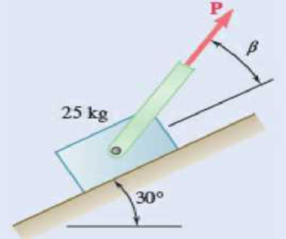
Fig. P8.F1
Expert Solution & Answer
Want to see the full answer?
Check out a sample textbook solution
Students have asked these similar questions
My ID# 016948724
last 2 ID# 24
Last 3 ID# 724
Please help to find the correct answer for this problem using my ID# first write le line of action and then help me to find the forces {fx= , fy= mz= and for the last find the moment of inertial about the show x and y axes please show how to solve step by step
My ID# 016948724
last 2 ID# 24
Last 3 ID# 724
Please help to find the correct answer for this problem using my ID# first write le line of action and then help me to find the forces and the tension {fx= , fy= mz=
My ID# 016948724
last 2 ID# 24
Last 3 ID# 724
Please help to find the correct answer for this problem using my ID# first write le line of action and then help me to find the forces {fx= , fy= mz=
Chapter 8 Solutions
Vector Mechanics for Engineers: Statics, 11th Edition
Ch. 8.1 - Knowing that the coefficient of friction between...Ch. 8.1 - Two blocks A and B are connected by a cable as...Ch. 8.1 - A cord is attached to and partially wound around a...Ch. 8.1 - A 40-kg packing crate must be moved to the left...Ch. 8.1 - 8.1 Determine whether the block shown is in...Ch. 8.1 - Prob. 8.2PCh. 8.1 - Prob. 8.3PCh. 8.1 - 8.4 Determine whether the block shown is in...Ch. 8.1 - Prob. 8.5PCh. 8.1 - The 20-lb block A hangs from a cable as shown....
Ch. 8.1 - The 10-kg block is attached to link AB and rests...Ch. 8.1 - Considering only values of less than 90,...Ch. 8.1 - Prob. 8.9PCh. 8.1 - 8.10 Knowing that P = 100 N, determine the range...Ch. 8.1 - The 50-lb block A and the 25-lb block B are...Ch. 8.1 - The 50-lb block A and the 25-lb block B are...Ch. 8.1 - Three 4-kg packages A, B, and C are placed on a...Ch. 8.1 - Solve Prob. 8.13 assuming that package B is placed...Ch. 8.1 - A uniform crate with a mass of 30 kg must be moved...Ch. 8.1 - A worker slowly moves a 50-kg crate to the left...Ch. 8.1 - Prob. 8.17PCh. 8.1 - 8.18 A 120-lb cabinet is mounted on casters that...Ch. 8.1 - Prob. 8.19PCh. 8.1 - Solve Prob. 8.19 assuming that the coefficients of...Ch. 8.1 - Prob. 8.21PCh. 8.1 - The cylinder shown has a weight W and radius r,...Ch. 8.1 - 8.23 and 8.24 End A of a slender, uniform rod with...Ch. 8.1 - Prob. 8.24PCh. 8.1 - A 6. 5-m ladder AB leans against a wall as shown....Ch. 8.1 - A 6. 5-m ladder AB leans against a wall as shown....Ch. 8.1 - The press shown is used to emboss a small seal at...Ch. 8.1 - The machine base shown has a mass of 75 kg and is...Ch. 8.1 - The 50-lb plate ABCD is attached at A and D to...Ch. 8.1 - In Prob. 8.29, determine the range of values of...Ch. 8.1 - A window sash weighing 10 lb is normally supported...Ch. 8.1 - A 500-N concrete block is to be lifted by the pair...Ch. 8.1 - Prob. 8.33PCh. 8.1 - Prob. 8.34PCh. 8.1 - Prob. 8.35PCh. 8.1 - Prob. 8.36PCh. 8.1 - A 1.2-m plank with a mass of 3 kg rests on two...Ch. 8.1 - Two identical uniform boards, each with a weight...Ch. 8.1 - Prob. 8.39PCh. 8.1 - Prob. 8.40PCh. 8.1 - A 10-ft beam, weighing 1200 lb, is to be moved to...Ch. 8.1 - (a) Show that the beam of Prob. 8.41 cannot be...Ch. 8.1 - Two 8-kg blocks A and B resting on shelves are...Ch. 8.1 - A slender steel rod with a length of 225 mm is...Ch. 8.1 - In Prob. 8.44, determine the smallest value of ...Ch. 8.1 - Two slender rods of negligible weight are...Ch. 8.1 - Two slender rods of negligible weight are...Ch. 8.2 - The machine part ABC is supported by a...Ch. 8.2 - Solve Prob. 8.48 assuming that the wedge is moved...Ch. 8.2 - Prob. 8.50PCh. 8.2 - Prob. 8.51PCh. 8.2 - The elevation of the end of the steel beam...Ch. 8.2 - Prob. 8.53PCh. 8.2 - Block A supports a pipe column and rests as shown...Ch. 8.2 - Block A supports a pipe column and rests as shown...Ch. 8.2 - Block A supports a pipe column and rests as shown...Ch. 8.2 - Prob. 8.57PCh. 8.2 - A 15 wedge is forced into a saw cut to prevent...Ch. 8.2 - A 12 wedge is used to spread a split ring. The...Ch. 8.2 - The spring of the door latch has a constant of 1.8...Ch. 8.2 - Prob. 8.61PCh. 8.2 - Prob. 8.62PCh. 8.2 - Prob. 8.63PCh. 8.2 - A 15 wedge is forced under a 50-kg pipe as shown....Ch. 8.2 - A 15 wedge is forced under a 50-kg pipe as shown....Ch. 8.2 - Prob. 8.66PCh. 8.2 - *8.67 Solve Prob. 8.66 assuming that the rollers...Ch. 8.2 - Derive the following formulas relating the load W...Ch. 8.2 - Prob. 8.69PCh. 8.2 - Prob. 8.70PCh. 8.2 - High-strength bolts are used in the construction...Ch. 8.2 - The position of the automobile jack shown is...Ch. 8.2 - For the jack of Prob. 8.72, determine the...Ch. 8.2 - Prob. 8.74PCh. 8.2 - Prob. 8.75PCh. 8.2 - Prob. 8.76PCh. 8.3 - A lever of negligible weight is loosely fitted...Ch. 8.3 - Prob. 8.78PCh. 8.3 - 8.79 and 8.80 The double pulley shown is attached...Ch. 8.3 - Prob. 8.80PCh. 8.3 - 8.81 and 8.82 The double pulley shown is attached...Ch. 8.3 - 8.81 and 8.82 The double pulley shown is attached...Ch. 8.3 - The block and tackle shown are used to raise a...Ch. 8.3 - The block and tackle shown are used to lower a...Ch. 8.3 - A scooter is to be designed to roll down a 2...Ch. 8.3 - The link arrangement shown is frequently used in...Ch. 8.3 - 8.87 and 8.88 A lever AB of negligible weight is...Ch. 8.3 - 8.87 and 8.88 A lever AB of negligible weight is...Ch. 8.3 - 8.89 and 8.90 A lever AB of negligible weight is...Ch. 8.3 - 8.89 and 8.90 A lever AB of negligible weight is...Ch. 8.3 - A loaded railroad car has a mass of 30 Mg and is...Ch. 8.3 - 8.92 Knowing that a couple of magnitude 30 N-m is...Ch. 8.3 - A 50-lb electric floor polisher is operated on a...Ch. 8.3 - The frictional resistance of a thrust bearing...Ch. 8.3 - Assuming that bearings wear out as indicated in...Ch. 8.3 - Assuming that the pressure between the surfaces of...Ch. 8.3 - Solve Prob. 8.93 assuming that the normal force...Ch. 8.3 - Determine the horizontal force required to move a...Ch. 8.3 - Knowing that a 6-in.-diameter disk rolls at a...Ch. 8.3 - A 900-kg machine base is rolled along a concrete...Ch. 8.3 - Solve Prob. 8.85 including the effect of a...Ch. 8.3 - Solve Prob. 8.91 including the effect of a...Ch. 8.4 - A rope having a weight per unit length of 0.4...Ch. 8.4 - 8.104 A hawser is wrapped two full turns around a...Ch. 8.4 - Two cylinders are connected by a rope that passes...Ch. 8.4 - Two cylinders are connected by a rope that passes...Ch. 8.4 - Prob. 8.107PCh. 8.4 - 8.108 Knowing that the coefficient of static...Ch. 8.4 - A band belt is used to control the speed of a...Ch. 8.4 - The setup shown is used to measure the output of a...Ch. 8.4 - The setup shown is used to measure the output of a...Ch. 8.4 - A flat belt is used to transmit a couple from drum...Ch. 8.4 - A flat belt is used to transmit a couple from...Ch. 8.4 - Prob. 8.114PCh. 8.4 - The speed of the brake drum shown is controlled by...Ch. 8.4 - Prob. 8.116PCh. 8.4 - The speed of the brake drum shown is controlled by...Ch. 8.4 - Bucket A and block C are connected by a cable that...Ch. 8.4 - Solve Prob. 8.118 assuming that drum B is frozen...Ch. 8.4 - Prob. 8.120PCh. 8.4 - 8.121 and 8.123 A cable is placed around three...Ch. 8.4 - Prob. 8.122PCh. 8.4 - 8.121 and 8.123 A cable is placed around three...Ch. 8.4 - A recording tape passes over the 20-mm-radius...Ch. 8.4 - Solve Prob. 8.124 assuming that the idler drum C...Ch. 8.4 - Prob. 8.126PCh. 8.4 - Prob. 8.127PCh. 8.4 - Prob. 8.128PCh. 8.4 - Prob. 8.129PCh. 8.4 - Prove that Eqs. (8.13) and (8.14) are valid for...Ch. 8.4 - Prob. 8.131PCh. 8.4 - Solve Prob. 8.112 assuming that the flat belt and...Ch. 8.4 - Solve Prob. 8.113 assuming that the flat belt and...Ch. 8 - 8.134 and 8.135 The coefficients of friction are S...Ch. 8 - 8.134 and 8.135 The coefficients of friction are S...Ch. 8 - A 120-lb cabinet is mounted on casters that can be...Ch. 8 - Prob. 8.137RPCh. 8 - The hydraulic cylinder shown exerts a force of 3...Ch. 8 - Prob. 8.139RPCh. 8 - Bar AB is attached to collars that can slide on...Ch. 8 - Two 10 wedges of negligible weight are used to...Ch. 8 - A 10 wedge is used to split a section of a log....Ch. 8 - In the gear-pulling assembly shown, the...Ch. 8 - A lever of negligible weight is loosely fitted...Ch. 8 - In the pivoted motor mount shown, the weight W of...
Knowledge Booster


Learn more about
Need a deep-dive on the concept behind this application? Look no further. Learn more about this topic, mechanical-engineering and related others by exploring similar questions and additional content below.Similar questions
- my ID is 016948724 Last 2 ID# 24 Last 3 ID# 724 please help me to solve this problem step by step show me how to solve first wirte the line actions and then find the forces {fx=, fy=, mz= and for the last step find the support reactions and find forcesarrow_forwardUppgift 1 (9p) 3 m 3 m 3 m 3 m H G F 3 m ↑ Dy D B AAY 30° 8 kN Ay Fackverket i figuren ovan är belastat med en punktlast. Bestäm normalkraften i stängerna BC, BG och FG.arrow_forwardThe cardiovascular countercurrent heat exchnager mechanism is to warm venous blood from 28 degrees C to 35 degrees C at a mass flow rate of 2 g/s. The artery inflow temp is 37 degrees C at a mass flow rate of 5 g/s. The average diameter of the vein is 5 cm and the overall heat transfer coefficient is 125 W/m^2*K. Determine the overall blood vessel length needed too warm the venous blood to 35 degrees C if the specific heat of both arterial and venous blood is constant and equal to 3475 J/kg*K.arrow_forward
- The forces Qy=12 kNQy=12kN and Qz=16 kNQz=16kN act on the profile at the shear center C. Calculate: a) Shear flow at point B (2 points)b) Shear stress at point D (3 points)arrow_forwardConsider the feedback controlled blending system shown below, which is designed to keep theoutlet concentration constant despite potential variations in the stream 1 composition. The density of all streamsis 920 kg/m3. At the nominal steady state, the flow rates of streams 1 and 2 are 950 and 425 kg/min,respectively, the liquid level in the tank is 1.3 m, the incoming mass fractions are x1 = 0.27, x2 = 0.54. Noticethe overflow line, indicating that the liquid level remains constant (i.e. any change in total inlet flow ratetranslates immediately to the same change in the outlet flow rate). You may assume the stream 1 flowrate andthe stream 2 composition are both constant. Use minutes as the time unit throughout this problem. d) Derive the first order process and disturbance transfer functions;Gp= Kp/(tou*s+1) and Gd=Kd/(tou*s+1) and calculate and list the values and units of the parameters. e) Using the given information, write the general forms of Gm, GIP, and Gv below(in terms of…arrow_forwarda) Briefly explain what ratio control is. Give an example of a common chemical engineering situation in whichratio control would be useful and for that example state exactly how ratio control works (what would bemeasured, what is set, and how the controller logic works).b) Briefly explain what cascade control is. Give an example of a common chemical engineering situation inwhich cascade control would be useful and for that example state exactly how cascade control works (whatwould be measured, what is set, and how the controller logic works).arrow_forward
- Determine the reaction force acting on the beam AB, given F = 680 N. 5 4 4 m 3 3 A B 30° 3 m F (N)arrow_forwardThe frame in the figure is made of an HEA 300 profile (E = 210 GPa, material S355).a) Determine the support reactions at point A. (1p)b) Sketch the bending moment diagram caused by the loading. (1p)c) Using the principle of virtual work (unit load method), calculate the vertical displacement at point B using moment diagrams. Also take into account the compression of the column. (3p)arrow_forward9 kN/m 6 kN/m 3 m 6 m Bestäm, med hjälp av friläggning och jämviktsberäkningar, tvärkrafts- och momentdiagram för balken i figuren. Extrempunkter ska anges med både läge och värde.arrow_forward
- B C 3.0 E F G 40 kN [m] 3.0 3.0 3.0 Fackverket belastas med en punktlast i G enligt figuren. Bestäm normalkraften i stängerna BC, BF och EF.arrow_forwardL q=8 kN/m P= 12 kN En stång belastas av en punklast P vid sin ena ände samt av en jämnt utbredd last q längs hela sin längd. Stången har en tvärsnittsarea A = 150 mm² och är tillverkad av stål med elasticitetsmodul E-210 GPa. Stångens längd, i sitt obelastade tillstånd, är Z-3 m. a) Hur stor är den största normalspänning som uppstår i stången? b) Hur stor blir förlängningen av stången, orsakad av lasterna P och q?arrow_forwardA turbocharged engine with a compression ratio of 8 is being designed using an air standard cycle. The ambient air is assumed to be 300K and 100 kPa. The temperature at the end of the compression in the cylinder is desired to be 1000K, assuming no combustion prior to reaching TDC. At the end of the cylinder expansion the temperature is also desired to be 1000K. If both the turbine and the compressor have mechanical efficiencies of 80%, what will be the pressure ratio of the compressor and what will be the turbine exhaust temperature?arrow_forward
arrow_back_ios
SEE MORE QUESTIONS
arrow_forward_ios
Recommended textbooks for you
 Elements Of ElectromagneticsMechanical EngineeringISBN:9780190698614Author:Sadiku, Matthew N. O.Publisher:Oxford University Press
 Mechanics of Materials (10th Edition)Mechanical EngineeringISBN:9780134319650Author:Russell C. HibbelerPublisher:PEARSON
 Thermodynamics: An Engineering ApproachMechanical EngineeringISBN:9781259822674Author:Yunus A. Cengel Dr., Michael A. BolesPublisher:McGraw-Hill Education
 Control Systems EngineeringMechanical EngineeringISBN:9781118170519Author:Norman S. NisePublisher:WILEY
 Mechanics of Materials (MindTap Course List)Mechanical EngineeringISBN:9781337093347Author:Barry J. Goodno, James M. GerePublisher:Cengage Learning
 Engineering Mechanics: StaticsMechanical EngineeringISBN:9781118807330Author:James L. Meriam, L. G. Kraige, J. N. BoltonPublisher:WILEY
Elements Of Electromagnetics
Mechanical Engineering
ISBN:9780190698614
Author:Sadiku, Matthew N. O.
Publisher:Oxford University Press
Mechanics of Materials (10th Edition)
Mechanical Engineering
ISBN:9780134319650
Author:Russell C. Hibbeler
Publisher:PEARSON
Thermodynamics: An Engineering Approach
Mechanical Engineering
ISBN:9781259822674
Author:Yunus A. Cengel Dr., Michael A. Boles
Publisher:McGraw-Hill Education
Control Systems Engineering
Mechanical Engineering
ISBN:9781118170519
Author:Norman S. Nise
Publisher:WILEY
Mechanics of Materials (MindTap Course List)
Mechanical Engineering
ISBN:9781337093347
Author:Barry J. Goodno, James M. Gere
Publisher:Cengage Learning
Engineering Mechanics: Statics
Mechanical Engineering
ISBN:9781118807330
Author:James L. Meriam, L. G. Kraige, J. N. Bolton
Publisher:WILEY
Differences between Temporary Joining and Permanent Joining.; Author: Academic Gain Tutorials;https://www.youtube.com/watch?v=PTr8QZhgXyg;License: Standard Youtube License