
Videos
How is a zener diode connected in a circuit as compared to a common junction diode?
The way in which the zener diode is connected in the circuit as compared to the junction diode.
Explanation of Solution
The PN junction is commonly known as the diode. The diode the electronic device that acts as a swtich and conducts in one direction only.
To forward bias the diode the P terminal is connected to the ANODE and the N type is connected to the cathode. Reverse of this is done to reverse bias the diode.
The symbol for the diode is shown below.
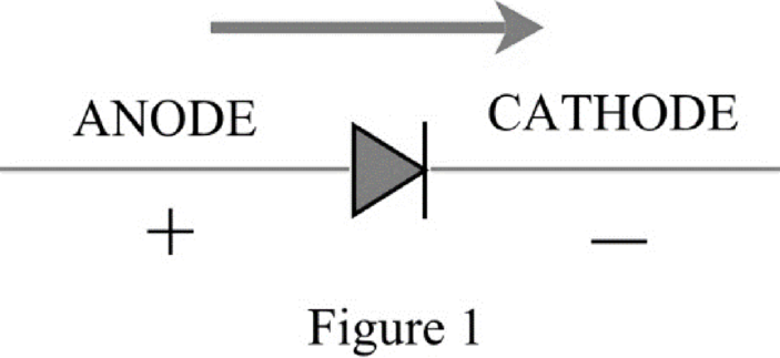
The diode operates like a swtich, when the diode is forward biased the current flows through it in one direction only that is from P terminal to N terminal. To reverse the diode the cathode is connected to P and anode to N, for ideal condition the diode do not conduct in reverse but there is a small amount of current through it that is called the leakage current.
The zener diode is the diode that can operate in the reverse biased and the region of operation in that case is called the zener region. The diode conducts when the diodes breaks down in the reverse direction known as avalanche.
Therefore, the zener diode is connected in the circuit in reverse polarity as compared to common junction diode.
Want to see more full solutions like this?


- Steam enters the high-pressure turbine of a steam power plant that operates on the ideal reheat Rankine cycle at 700 psia and 900°F and leaves as saturated vapor. Steam is then reheated to 800°F before it expands to a pressure of 1 psia. Heat is transferred to the steam in the boiler at a rate of 6 × 10⁴ Btu/s. Steam is cooled in the condenser by the cooling water from a nearby river, which enters the condenser at 45°F. Use steam tables. NOTE: This is a multi-part question. Once an answer is submitted, you will be unable to return to this part. Determine the pressure at which reheating takes place. Use steam tables. Find: The reheat pressure is psia. (P4)Find thermal efficiencyFind m dotarrow_forwardAir at T1 = 24°C, p1 = 1 bar, 50% relative humidity enters an insulated chamber operating at steady state with a mass flow rate of 3 kg/min and mixes with a saturated moist air stream entering at T2 = 7°C, p2 = 1 bar. A single mixed stream exits at T3 = 17°C, p3 = 1 bar. Neglect kinetic and potential energy effects Determine mass flow rate of the moist air entering at state 2, in kg/min Determine the relative humidity of the exiting stream. Determine the rate of entropy production, in kJ/min.Karrow_forwardAir at T1 = 24°C, p1 = 1 bar, 50% relative humidity enters an insulated chamber operating at steady state with a mass flow rate of 3 kg/min and mixes with a saturated moist air stream entering at T2 = 7°C, p2 = 1 bar. A single mixed stream exits at T3 = 17°C, p3 = 1 bar. Neglect kinetic and potential energy effects Determine mass flow rate of the moist air entering at state 2, in kg/min Determine the relative humidity of the exiting stream. Determine the rate of entropy production, in kJ/min.Karrow_forward
- Air at T1 = 24°C, p1 = 1 bar, 50% relative humidity enters an insulated chamber operating at steady state with a mass flow rate of 3 kg/min and mixes with a saturated moist air stream entering at T2 = 7°C, p2 = 1 bar. A single mixed stream exits at T3 = 17°C, p3 = 1 bar. Neglect kinetic and potential energy effects (a) Determine mass flow rate of the moist air entering at state 2, in kg/min (b) Determine the relative humidity of the exiting stream. (c) Determine the rate of entropy production, in kJ/min.Karrow_forwardA simple ideal Brayton cycle operates with air with minimum and maximum temperatures of 27°C and 727°C. It is designed so that the maximum cycle pressure is 2000 kPa and the minimum cycle pressure is 100 kPa. The isentropic efficiencies of the turbine and compressor are 91% and 80%, respectively, and there is a 50 kPa pressure drop across the combustion chamber. Determine the net work produced per unit mass of air each time this cycle is executed and the cycle’s thermal efficiency. Use constant specific heats at room temperature. The properties of air at room temperature are cp = 1.005 kJ/kg·K and k = 1.4. The fluid flow through the cycle is in a clockwise direction from point 1 to 4. Heat Q sub in is given to a component between points 2 and 3 of the cycle. Heat Q sub out is given out by a component between points 1 and 4. An arrow from the turbine labeled as W sub net points to the right. The net work produced per unit mass of air is kJ/kg. The thermal efficiency is %.arrow_forwardSteam enters the high-pressure turbine of a steam power plant that operates on the ideal reheat Rankine cycle at 700 psia and 900°F and leaves as saturated vapor. Steam is then reheated to 800°F before it expands to a pressure of 1 psia. Heat is transferred to the steam in the boiler at a rate of 6 × 10⁴ Btu/s. Steam is cooled in the condenser by the cooling water from a nearby river, which enters the condenser at 45°F. Use steam tables. NOTE: This is a multi-part question. Once an answer is submitted, you will be unable to return to this part. Determine the pressure at which reheating takes place. Use steam tables. The reheat pressure is psia.Find thermal efficieny Find m dotarrow_forward
- This is an old exam practice question.arrow_forwardAs shown in the figure below, moist air at T₁ = 36°C, 1 bar, and 35% relative humidity enters a heat exchanger operating at steady state with a volumetric flow rate of 10 m³/min and is cooled at constant pressure to 22°C. Ignoring kinetic and potential energy effects, determine: (a) the dew point temperature at the inlet, in °C. (b) the mass flow rate of moist air at the exit, in kg/min. (c) the relative humidity at the exit. (d) the rate of heat transfer from the moist air stream, in kW. (AV)1, T1 P₁ = 1 bar 11 = 35% 120 T₂=22°C P2 = 1 bararrow_forwardAir at T₁-24°C, p₁-1 bar, 50% relative humidity enters an insulated chamber operating at steady state with a mass flow rate of 3 kg/min and mixes with a saturated moist air stream entering at T₂-7°C, p2-1 bar. A single mixed stream exits at T3-17°C, p3-1 bar. Neglect kinetic and potential energy effects Step 1 Your answer is correct. Determine mass flow rate of the moist air entering at state 2, in kg/min. m2 = 2.1 Hint kg/min Using multiple attempts will impact your score. 5% score reduction after attempt 2 Step 2 Determine the relative humidity of the exiting stream. Փ3 = i % Attempts: 1 of 3 usedarrow_forward
- A reservoir at 300 ft elevation has a 6-in.-diameter discharge pipe located 50 ft below the surface. The pipe is 600 ft long and drops in elevation to 150 ft where the flow discharges to the atmosphere. The pipe is made of riveted steel with a roughness height of 0.005 ft. Determine the flow rate without a head loss Determine the flow rate with the pipe friction head loss. (hints: Since the velocity is not known for part b and the Reynolds number and friction factor depend on velocity, you will need to iterate to find the solution. A good first guess is the velocity from part (a))arrow_forwardAir at T₁-24°C, p₁-1 bar, 50% relative humidity enters an insulated chamber operating at steady state with a mass flow rate of 3 kg/min and mixes with a saturated moist air stream entering at T₂-7°C, p2-1 bar. A single mixed stream exits at T3-17°C, p3-1 bar. Neglect kinetic and potential energy effects Step 1 Your answer is correct. Determine mass flow rate of the moist air entering at state 2, in kg/min. m2 = 2.1 Hint kg/min Using multiple attempts will impact your score. 5% score reduction after attempt 2 Step 2 Determine the relative humidity of the exiting stream. Փ3 = i % Attempts: 1 of 3 usedarrow_forward25 mm Brass core E = 105 GPa 0 = 20.9 x 10 °C PROBLEM 2.49 The aluminum shell is fully bonded to the brass core and the assembly is unstressed at a temperature of 15°C. Considering only axial deformations, determine the stress in the aluminum when the temperature reaches 195°C. 60 mm Aluminum shell E = 70 GPa a = 23.6 × 10°Carrow_forward
 Understanding Motor ControlsMechanical EngineeringISBN:9781337798686Author:Stephen L. HermanPublisher:Delmar Cengage Learning
 Refrigeration and Air Conditioning Technology (Mi...Mechanical EngineeringISBN:9781305578296Author:John Tomczyk, Eugene Silberstein, Bill Whitman, Bill JohnsonPublisher:Cengage Learning
 Electrical Transformers and Rotating MachinesMechanical EngineeringISBN:9781305494817Author:Stephen L. HermanPublisher:Cengage Learning
 Automotive Technology: A Systems Approach (MindTa...Mechanical EngineeringISBN:9781133612315Author:Jack Erjavec, Rob ThompsonPublisher:Cengage Learning