
Engineering Mechanics: Statics & Dynamics (14th Edition)
14th Edition
ISBN: 9780133915426
Author: Russell C. Hibbeler
Publisher: PEARSON
expand_more
expand_more
format_list_bulleted
Videos
Textbook Question
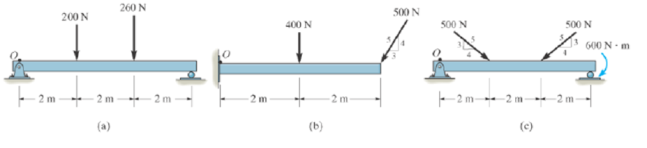
Chapter 4.8, Problem 6PP
In each case, determine the x and y components of the resultant force and specify the distance where this force acts from point O.
Expert Solution & Answer
Want to see the full answer?
Check out a sample textbook solution
Students have asked these similar questions
2. Find a basis of solutions by the Frobenius method. Try to identify the series as expansions of
known functions.
(x + 2)²y" + (x + 2)y' - y = 0 ; Hint: Let: z = x+2
1. Find a power series solution in powers of x.
y" - y' + x²y = 0
3. Find a basis of solutions by the Frobenius method. Try to identify the series as expansions of
known functions.
8x2y" +10xy' + (x 1)y = 0
-
Chapter 4 Solutions
Engineering Mechanics: Statics & Dynamics (14th Edition)
Ch. 4.4 - In each case, determine the moment of the force...Ch. 4.4 - In each case, set up the determinant to find the...Ch. 4.4 - Determine the moment of the force about point O.Ch. 4.4 - Determine the moment of the force about point O.Ch. 4.4 - Determine the moment of the force about point O.Ch. 4.4 - Determine the moment of the force about point O....Ch. 4.4 - Determine the moment of the force about point O.Ch. 4.4 - Determine the moment of the force about point O.Ch. 4.4 - Determine the resultant moment produced by the...Ch. 4.4 - Determine the resultant moment produced by the...
Ch. 4.4 - Determine the resultant moment produced by the...Ch. 4.4 - Determine the moment of force F about point O....Ch. 4.4 - Prob. 11FPCh. 4.4 - Prob. 12FPCh. 4.4 - Prob. 1PCh. 4.4 - Prove the triple scalar product identity A (B C)...Ch. 4.4 - Prob. 3PCh. 4.4 - Prob. 4PCh. 4.4 - Determine the moment about point B of each of the...Ch. 4.4 - The crowbar is subjected to a vertical force of P...Ch. 4.4 - Determine the moment of each of the three forces...Ch. 4.4 - Determine the moment of each of the three forces...Ch. 4.4 - Determine the moment of each force about the bolt...Ch. 4.4 - If FB = 30 lb and FC = 45 lb, determine the...Ch. 4.4 - Prob. 11PCh. 4.4 - The towline exerts a force of P = 6 kN at the end...Ch. 4.4 - Prob. 13PCh. 4.4 - The 20-N horizontal force acts on the handle of...Ch. 4.4 - Two men exert forces of F = 80 lb and P = 50 lb on...Ch. 4.4 - Prob. 16PCh. 4.4 - Prob. 17PCh. 4.4 - The tongs are used to grip the ends of the...Ch. 4.4 - Prob. 19PCh. 4.4 - The handle of the hammer is subjected to the force...Ch. 4.4 - In order to pull out the nail at B, the force F...Ch. 4.4 - Old clocks were constructed using a fusee B to...Ch. 4.4 - The tower crane is used to hoist the 2-Mg load...Ch. 4.4 - The tower crane is used to hoist a 2-Mg load...Ch. 4.4 - If the 1500-lb boom AB, the 200-lb cage BCD, and...Ch. 4.4 - If the 1500-lb boom AB, the 200-lb cage BCD, and...Ch. 4.4 - Determine the moment of the force F about point O....Ch. 4.4 - Determine the moment of the force F about point P....Ch. 4.4 - The force F = {400i 100j 700k} lb acts at the...Ch. 4.4 - The force F = {400i 100j 700k} lb acts at the end...Ch. 4.4 - Determine the moment of the force F about point P....Ch. 4.4 - The pipe assembly is subjected to the force of F =...Ch. 4.4 - The pipe assembly is subjected to the force of F =...Ch. 4.4 - Determine the moment of the force of F = 600 N...Ch. 4.4 - Determine the smallest force F that must be...Ch. 4.4 - Determine the coordinate direction angles , , of...Ch. 4.4 - Determine the moment of force F about point O. The...Ch. 4.4 - Determine the moment of the force F about the door...Ch. 4.4 - Determine the moment of the force F about the door...Ch. 4.4 - Determine the smallest force F that must be...Ch. 4.4 - Prob. 41PCh. 4.4 - A 20-N horizontal force is applied perpendicular...Ch. 4.4 - Prob. 43PCh. 4.4 - The pipe assembly is subjected to the 80-N force....Ch. 4.4 - Prob. 45PCh. 4.4 - Prob. 46PCh. 4.4 - Prob. 47PCh. 4.4 - Prob. 48PCh. 4.4 - Prob. 49PCh. 4.4 - Prob. 50PCh. 4.4 - Using a ring collar, the 75-N force can act in the...Ch. 4.5 - In each case, determine the resultant moment of...Ch. 4.5 - Prob. 4PPCh. 4.5 - Prob. 13FPCh. 4.5 - Prob. 14FPCh. 4.5 - Determine the magnitude of the moment of the 200-N...Ch. 4.5 - Determine the magnitude of the moment of the force...Ch. 4.5 - Prob. 17FPCh. 4.5 - Determine the moment of force F about the x, the...Ch. 4.5 - The lug nut on the wheel of the automobile is to...Ch. 4.5 - Solve Prob. 4-52 if the cheater pipe AB is slipped...Ch. 4.5 - The A-frame is being hoisted into an upright...Ch. 4.5 - Prob. 55PCh. 4.5 - Determine the magnitude of the moments of the...Ch. 4.5 - Determine the moment of this force F about an axis...Ch. 4.5 - Prob. 58PCh. 4.5 - Prob. 59PCh. 4.5 - Prob. 60PCh. 4.5 - Determine the magnitude of the moment of the force...Ch. 4.5 - Determine the magnitude of the moment of the force...Ch. 4.5 - Determine the magnitude of the moment of the force...Ch. 4.5 - A horizontal force of F = {50i} N is applied...Ch. 4.5 - Prob. 65PCh. 4.5 - Prob. 66PCh. 4.6 - Determine the resultant couple moment acting on...Ch. 4.6 - Determine the resultant couple moment acting on...Ch. 4.6 - Prob. 21FPCh. 4.6 - Determine the couple moment acting on the beam.Ch. 4.6 - Determine the resultant couple moment acting on...Ch. 4.6 - Determine the couple moment acting on the pipe...Ch. 4.6 - Prob. 67PCh. 4.6 - Prob. 68PCh. 4.6 - If the resultant couple of the three couples...Ch. 4.6 - Two couples act on the beam. If F = 125 lb,...Ch. 4.6 - Two couples act on the beam. Determine the...Ch. 4.6 - Determine the magnitude of the couple forces F so...Ch. 4.6 - Prob. 73PCh. 4.6 - Prob. 74PCh. 4.6 - Prob. 75PCh. 4.6 - Determine the magnitude of F so that the resultant...Ch. 4.6 - Prob. 77PCh. 4.6 - Prob. 78PCh. 4.6 - Two couples act on the frame. If the resultant...Ch. 4.6 - Prob. 80PCh. 4.6 - Two couples act on the frame. If d = 4 ft,...Ch. 4.6 - Prob. 82PCh. 4.6 - If M1 = 180 lb ft, M2 = 90 lb ft, and M3 = 120...Ch. 4.6 - Prob. 84PCh. 4.6 - The gears are subjected to the couple moments...Ch. 4.6 - Determine the required magnitude of the couple...Ch. 4.6 - Determine the resultant couple moment of the two...Ch. 4.6 - Express the moment of the couple acting on the...Ch. 4.6 - In order to turn over the frame, a couple moment...Ch. 4.6 - Express the moment of the couple acting on the...Ch. 4.6 - If the couple moment acting on the pipe has a...Ch. 4.6 - If F = 80 N, determine the magnitude and...Ch. 4.6 - If the magnitude of the couple moment acting on...Ch. 4.6 - Express the moment of the couple acting on the rod...Ch. 4.6 - If F1 = 100 N, F2 = 120 N, and F3 = 80 N,...Ch. 4.6 - Prob. 96PCh. 4.7 - In each case, determine the x and y components of...Ch. 4.7 - F-25. Replace the leading system by an equivalent...Ch. 4.7 - F-26. Replace the loading system by an equivalent...Ch. 4.7 - Prob. 27FPCh. 4.7 - Prob. 28FPCh. 4.7 - Prob. 29FPCh. 4.7 - F-30. Replace the loading system by an equivalent...Ch. 4.7 - Replace the force system by an equivalent...Ch. 4.7 - Prob. 98PCh. 4.7 - Prob. 99PCh. 4.7 - Prob. 100PCh. 4.7 - Replace the loading system acting on the beam by...Ch. 4.7 - Prob. 102PCh. 4.7 - Prob. 103PCh. 4.7 - Prob. 104PCh. 4.7 - Replace the force system acting on the frame by an...Ch. 4.7 - Prob. 106PCh. 4.7 - Prob. 107PCh. 4.7 - Replace the force system by an equivalent...Ch. 4.7 - Prob. 109PCh. 4.7 - Prob. 110PCh. 4.7 - Prob. 111PCh. 4.7 - Prob. 112PCh. 4.8 - In each case, determine the x and y components of...Ch. 4.8 - Prob. 7PPCh. 4.8 - Replace the loading system by an equivalent...Ch. 4.8 - Prob. 32FPCh. 4.8 - Prob. 33FPCh. 4.8 - Prob. 34FPCh. 4.8 - Prob. 35FPCh. 4.8 - Prob. 36FPCh. 4.8 - Prob. 113PCh. 4.8 - Prob. 114PCh. 4.8 - Prob. 115PCh. 4.8 - Prob. 116PCh. 4.8 - Replace the loading acting on the beam by a single...Ch. 4.8 - Prob. 118PCh. 4.8 - Prob. 119PCh. 4.8 - Prob. 120PCh. 4.8 - Prob. 121PCh. 4.8 - Prob. 122PCh. 4.8 - Prob. 123PCh. 4.8 - Prob. 124PCh. 4.8 - Prob. 125PCh. 4.8 - Replace the force and couple system acting on the...Ch. 4.8 - If FA = 7 kN and FB = 5 kN, represent the force...Ch. 4.8 - Determine the magnitudes of FA and FB so that the...Ch. 4.8 - Prob. 129PCh. 4.8 - Prob. 130PCh. 4.8 - Prob. 131PCh. 4.8 - If FA= 40 kN and FB = 35 kN, determine the...Ch. 4.8 - If the resultant force is required to act at the...Ch. 4.8 - Prob. 134PCh. 4.8 - Replace the force system by a wrench and specify...Ch. 4.8 - Prob. 136PCh. 4.8 - Replace the three forces acting on the plate by a...Ch. 4.9 - Determine the resultant force and specify where it...Ch. 4.9 - Prob. 38FPCh. 4.9 - Prob. 39FPCh. 4.9 - Determine the resultant force and specify where it...Ch. 4.9 - Prob. 41FPCh. 4.9 - Prob. 42FPCh. 4.9 - Replace the loading by an equivalent resultant...Ch. 4.9 - Replace the distributed loading with an equivalent...Ch. 4.9 - Prob. 140PCh. 4.9 - Prob. 141PCh. 4.9 - Replace the distributed loading by an equivalent...Ch. 4.9 - Replace this loading by an equivalent resultant...Ch. 4.9 - The distribution of soil loading on the bottom of...Ch. 4.9 - Replace the loading by an equivalent resultant...Ch. 4.9 - Replace the distributed loading by an equivalent...Ch. 4.9 - Prob. 147PCh. 4.9 - Prob. 148PCh. 4.9 - If the soil exerts a trapezoidal distribution of...Ch. 4.9 - Prob. 150PCh. 4.9 - Prob. 151PCh. 4.9 - Prob. 152PCh. 4.9 - Replace the leading by a single resultant force,...Ch. 4.9 - Prob. 154PCh. 4.9 - Replace the distributed loading by an equivalent...Ch. 4.9 - Prob. 156PCh. 4.9 - Prob. 157PCh. 4.9 - Prob. 158PCh. 4.9 - The distributed load acts on the shaft as shown....Ch. 4.9 - Replace the distributed loading with an equivalent...Ch. 4.9 - Prob. 161PCh. 4.9 - Prob. 162PCh. 4.9 - Prob. 1RPCh. 4.9 - Replace the force F having a magnitude of F = 50...Ch. 4.9 - Prob. 3RPCh. 4.9 - Prob. 4RPCh. 4.9 - Prob. 5RPCh. 4.9 - Prob. 6RPCh. 4.9 - Prob. 7RPCh. 4.9 - Prob. 8RP
Knowledge Booster


Learn more about
Need a deep-dive on the concept behind this application? Look no further. Learn more about this topic, mechanical-engineering and related others by exploring similar questions and additional content below.Similar questions
- Hello I was going over the solution for this probem and I'm a bit confused on the last part. Can you please explain to me 1^4 was used for the Co of the tubular cross section? Thank you!arrow_forwardBlood (HD = 0.45 in large diameter tubes) is forced through hollow fiber tubes that are 20 µm in diameter.Equating the volumetric flowrate expressions from (1) assuming marginal zone theory and (2) using an apparentviscosity for the blood, estimate the marginal zone thickness at this diameter. The viscosity of plasma is 1.2 cParrow_forwardQ2: Find the shear load on bolt A for the connection shown in Figure 2. Dimensions are in mm Fig. 2 24 0-0 0-0 A 180kN (10 Markarrow_forward
- determine the direction and magnitude of angular velocity ω3 of link CD in the four-bar linkage using the relative velocity graphical methodarrow_forwardFour-bar linkage mechanism, AB=40mm, BC=60mm, CD=70mm, AD=80mm, =60°, w1=10rad/s. Determine the direction and magnitude of w3 using relative motion graphical method. A B 2 3 77777 477777arrow_forwardFour-bar linkage mechanism, AB=40mm, BC=60mm, CD=70mm, AD=80mm, =60°, w1=10rad/s. Determine the direction and magnitude of w3 using relative motion graphical method. A B 2 3 77777 477777arrow_forward
- The evaporator of a vapor compression refrigeration cycle utilizing R-123 as the refrigerant isbeing used to chill water. The evaporator is a shell and tube heat exchanger with the water flowingthrough the tubes. The water enters the heat exchanger at a temperature of 54°F. The approachtemperature difference of the evaporator is 3°R. The evaporating pressure of the refrigeration cycleis 4.8 psia and the condensing pressure is 75 psia. The refrigerant is flowing through the cycle witha flow rate of 18,000 lbm/hr. The R-123 leaves the evaporator as a saturated vapor and leaves thecondenser as a saturated liquid. Determine the following:a. The outlet temperature of the chilled waterb. The volumetric flow rate of the chilled water (gpm)c. The UA product of the evaporator (Btu/h-°F)d. The heat transfer rate between the refrigerant and the water (tons)arrow_forward(Read image) (Answer given)arrow_forwardProblem (17): water flowing in an open channel of a rectangular cross-section with width (b) transitions from a mild slope to a steep slope (i.e., from subcritical to supercritical flow) with normal water depths of (y₁) and (y2), respectively. Given the values of y₁ [m], y₂ [m], and b [m], calculate the discharge in the channel (Q) in [Lit/s]. Givens: y1 = 4.112 m y2 = 0.387 m b = 0.942 m Answers: ( 1 ) 1880.186 lit/s ( 2 ) 4042.945 lit/s ( 3 ) 2553.11 lit/s ( 4 ) 3130.448 lit/sarrow_forward
- Problem (14): A pump is being used to lift water from an underground tank through a pipe of diameter (d) at discharge (Q). The total head loss until the pump entrance can be calculated as (h₁ = K[V²/2g]), h where (V) is the flow velocity in the pipe. The elevation difference between the pump and tank surface is (h). Given the values of h [cm], d [cm], and K [-], calculate the maximum discharge Q [Lit/s] beyond which cavitation would take place at the pump entrance. Assume Turbulent flow conditions. Givens: h = 120.31 cm d = 14.455 cm K = 8.976 Q Answers: (1) 94.917 lit/s (2) 49.048 lit/s ( 3 ) 80.722 lit/s 68.588 lit/s 4arrow_forwardProblem (13): A pump is being used to lift water from the bottom tank to the top tank in a galvanized iron pipe at a discharge (Q). The length and diameter of the pipe section from the bottom tank to the pump are (L₁) and (d₁), respectively. The length and diameter of the pipe section from the pump to the top tank are (L2) and (d2), respectively. Given the values of Q [L/s], L₁ [m], d₁ [m], L₂ [m], d₂ [m], calculate total head loss due to friction (i.e., major loss) in the pipe (hmajor-loss) in [cm]. Givens: L₁,d₁ Pump L₂,d2 오 0.533 lit/s L1 = 6920.729 m d1 = 1.065 m L2 = 70.946 m d2 0.072 m Answers: (1) 3.069 cm (2) 3.914 cm ( 3 ) 2.519 cm ( 4 ) 1.855 cm TABLE 8.1 Equivalent Roughness for New Pipes Pipe Riveted steel Concrete Wood stave Cast iron Galvanized iron Equivalent Roughness, & Feet Millimeters 0.003-0.03 0.9-9.0 0.001-0.01 0.3-3.0 0.0006-0.003 0.18-0.9 0.00085 0.26 0.0005 0.15 0.045 0.000005 0.0015 0.0 (smooth) 0.0 (smooth) Commercial steel or wrought iron 0.00015 Drawn…arrow_forwardThe flow rate is 12.275 Liters/s and the diameter is 6.266 cm.arrow_forward
arrow_back_ios
SEE MORE QUESTIONS
arrow_forward_ios
Recommended textbooks for you
 International Edition---engineering Mechanics: St...Mechanical EngineeringISBN:9781305501607Author:Andrew Pytel And Jaan KiusalaasPublisher:CENGAGE L
International Edition---engineering Mechanics: St...
Mechanical Engineering
ISBN:9781305501607
Author:Andrew Pytel And Jaan Kiusalaas
Publisher:CENGAGE L
How to balance a see saw using moments example problem; Author: Engineer4Free;https://www.youtube.com/watch?v=d7tX37j-iHU;License: Standard Youtube License