
Concept explainers
Videos
For the sets of given stresses on an element given in Table4−2, draw a complete Mohr’s circle, find the principal stresses and the maximum shear stress, and draw the principal stress element and the maximum shear stress element. Any stress components not shown are assumed to be zero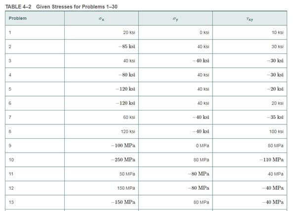
To draw: Mohr’s circle to determine the principal stresses and maximum shear stress. Also, draw the maximum shear stress element and principal stress element.
Answer to Problem 1P
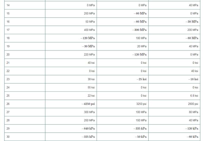
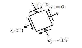
A complete Mohr’s circle is given as below,
The maximum principal stress is
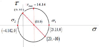
The principal stress element is given as,
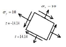
The maximum shear stress element is given as,

Explanation of Solution
Given Information:
Write the stresses in the x-direction, y-direction, and shear stress in the x-y plane.
Calculate the center of Mohr’s circle.
Calculate the radius of Mohr’s circle.
Draw the complete Mohr’s circle diagram.

Write the expression of principal stresses.
Substitute
Write the expression of maximum shear stress.
Substitute
Draw the principal stress elements.
Draw the maximum shear stress element.
Want to see more full solutions like this?
Chapter 4 Solutions
Machine Elements in Mechanical Design (6th Edition) (What's New in Trades & Technology)
Additional Engineering Textbook Solutions
Thermodynamics: An Engineering Approach
Vector Mechanics for Engineers: Statics and Dynamics
Management Information Systems: Managing The Digital Firm (16th Edition)
Mechanics of Materials (10th Edition)
Java How to Program, Early Objects (11th Edition) (Deitel: How to Program)


- Thermodynamics: Mass and Energy Analysis Of Control Volumes 1.5-kg of water that is initially at 90◦C with a quality of 5 percent occupies a spring-loaded piston-cylinder device. This device is now heated until the pressure rises to 900 kPa and the temperature is 280◦C. Determinethe total work produced during this process, in kJ.arrow_forwardThermodynamics: Mass and Energy Analysis Of Control Volumes Stainless steel ball bearings (ρ = 8085 kg/m3 and cp = 0.480 kJ/(kg◦C)) having a diameter of 1.5 cm areto be quenched in water at a rate of 900 per minute. The balls leave the oven at a uniform temperature of1000◦C and are exposed to air at 25◦C for a while before they are dropped into the water. If the temperatureof the balls drops to 900◦C prior to quenching, determine the rate of heat transfer from the balls to the air.arrow_forwardThermodynamics: Mass and Energy Analysis Of Control Volumes A 12-ft3 tank contains oxygen at 15 psia and 80◦F. A paddle wheel within the tank is rotated until thepressure inside rises to 20 psia. During the process 25 Btu of heat is lost to the surroundings. Determine thepaddle wheel work done. Neglect the energy stored in the paddle wheel.arrow_forward
- Thermodynamics: Mass and Energy Analysis Of Control Volumes A frictionless piston-cylinder device contains 4.5 kg of nitrogen at 110 kPa and 200 K. Nitrogen is nowcompressed slowly according to the relation PV1.5 = constant until it reaches a final temperature of 360 K.Calculate the work input during the process, in kJ.arrow_forwardThermodynamics: Mass and Energy Analysis Of Control Volumes An insulated piston-cylinder device contains 4 L of saturated liquid water at a constant pressure of 200 kPa.Water is stirred by a paddle wheel while a current of 8 A flows for 50 min through a resistor placed in thewater. If one-half of the liquid is evaporated during this constant-pressure process and the paddle-wheelwork amounts to 300 kJ, determine the voltage of the source. Also, show the process on a P–v diagram withrespect to the saturation lines.arrow_forwardThermodynamics: Mass and Energy Analysis Of Control Volumes The state of liquid water is changed from 55 psia and 45◦F to 2000 psia and 120◦F. Determine the change inthe internal energy and enthalpy of water on the basis of the (a) compressed liquid tables, (b) incompressiblesubstance approximation and property tables, and (c) specific-heat model.arrow_forward
- Thermodynamics: Mass and Energy Analysis Of Control Volumes What is the change in enthalpy, in kJ/kg, of oxygen as its temperature changes from 150 to 250◦C? Is thereany difference if the temperature change were from −50 to 100◦C? Does the pressure at the beginning andend of this process have any effect on the enthalpy change?arrow_forwardThermodynamics: Mass and Energy Analysis Of Control Volumes A 50-L electrical radiator containing heating oil is placed in a 50-m3 room. Both the room and the oil in theradiator are initially at 5◦C. The radiator with a rating of 3 kW is now turned on. At the same time, heatis lost from the room at an average rate of 0.3 kJ/s. After some time, the average temperature is measuredto be 20◦C for the air in the room, and 60◦C for the oil in the radiator. Taking the density and the specificheat of the oil to be 950 kg/m3 and 2.2 kJ/(kg◦C), respectively, determine how long the heater is kept on.Assume the room is well-sealed so that there are no air leaks.arrow_forwardProblem 3 For the beam and loading shown, consider section n-n and determine (a) the largest shearing stress in that section, (b) the shearing stress at point a. 1ft 15 kips 20 kips 15 kips AITT in 1 0.6 in. -10 in. 1 in. 0.375 in.- 2 ft 2ft 2 ft 2ft 10 in. 1 0.6 in.arrow_forward
- practice problems want detailed break downarrow_forward6.105. Determine force P on the cable if the spring is compressed 0.025 m when the mechanism is in the position shown. The spring has a stiffness of k = 6 kN/m. E P 150 mm D T 30° 200 mm 200 mm 200 mm B 800 mmarrow_forward6.71. Determine the reactions at the supports A, C, and E of the compound beam. 3 kN/m 12 kN A B CD E -3 m 4 m 6 m 3 m 2 marrow_forward
 Mechanics of Materials (MindTap Course List)Mechanical EngineeringISBN:9781337093347Author:Barry J. Goodno, James M. GerePublisher:Cengage Learning