
Mechanics of Materials
11th Edition
ISBN: 9780137605460
Author: Russell C. Hibbeler
Publisher: Pearson Education (US)
expand_more
expand_more
format_list_bulleted
Videos
Textbook Question
Chapter 3.7, Problem 27P
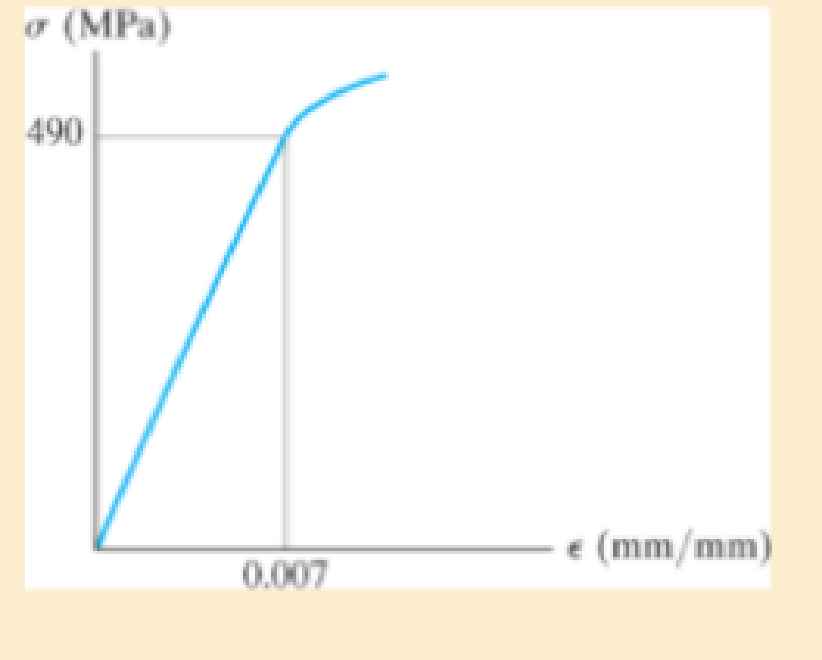
The elastic portion of the stress-strain diagram for an aluminum alloy is shown in the figure. The specimen from which it was obtained has an original diameter of 12.7 mm and a gage length of 50.8 mm. When the applied load on the specimen is 50 kN, the diameter is 12.67494 mm. Determine Poisson’s ratio for the material.
Expert Solution & Answer
Want to see the full answer?
Check out a sample textbook solution
Students have asked these similar questions
I don't want an AI solution please.
1.7 Find the stress distribution in the beam shown in Fig. 1.23 using two beam elements.
A. E. I constant
M₂
T
+
FIGURE 1.23 A fixed-pinned beam subjected to a moment
42 PART 1 Introduction
A. E. I constant
FIGURE 1.22 A fixed-pinned beam.
1.6 Find the stress distribution in the beam shown in Fig. 1.22 using two beam elements.
Chapter 3 Solutions
Mechanics of Materials
Ch. 3.4 - Define a homogeneous material.Ch. 3.4 - Indicate the points on the stress-strain diagram...Ch. 3.4 - Define the modulus of elasticity E.Ch. 3.4 - At room temperature, mild steel is a ductile...Ch. 3.4 - Engineering stress and strain are calculated using...Ch. 3.4 - As the temperature increases the modulus of...Ch. 3.4 - A 100-mm-long rod has a diameter of 15 mm. If an...Ch. 3.4 - A bar has a length of 8 in. and cross-sectional...Ch. 3.4 - A 10-mm-diameter rod has a modulus of elasticity...Ch. 3.4 - The material for the 50-mm-long specimen has the...
Ch. 3.4 - The material for the 50-mm-long specimen has the...Ch. 3.4 - If the elongation of wire BC is 0.2 mm after the...Ch. 3.4 - Data taken from a stress-strain test for a ceramic...Ch. 3.4 - The stress-strain diagram for a steel alloy having...Ch. 3.4 - The stress-strain diagram for a steel alloy having...Ch. 3.4 - The stress-strain diagram for a steel alloy having...Ch. 3.4 - Determine the elongation of the square hollow bar...Ch. 3.4 - The stress-strain diagram for an aluminum alloy...Ch. 3.4 - The stress-strain diagram for an aluminum alloy...Ch. 3.4 - The stress-strain diagram for an aluminum alloy...Ch. 3.4 - A structural member in a nuclear reactor is made...Ch. 3.4 - The rigid pipe is supported by a pin at A and an...Ch. 3.4 - The rigid pipe is supported by a pin at A and an...Ch. 3.4 - Direct tension indicators are sometimes used...Ch. 3.4 - A tension test was performed on a magnesium alloy...Ch. 3.4 - The stress-strain diagram for a bone is shown and...Ch. 3.4 - The two bars are made of a material that has the...Ch. 3.4 - The two bars are made of a material that has the...Ch. 3.7 - A 100-mm-long rod has a diameter of 15 mm. If an...Ch. 3.7 - A solid circular rod that is 600 mm long and 20 mm...Ch. 3.7 - A 20-mm-wide block is firmly bonded to rigid...Ch. 3.7 - A 20-mm-wide block is bonded to rigid plates at...Ch. 3.7 - The acrylic plastic rod is 400mm long and 20mm in...Ch. 3.7 - The elastic portion of the stress-strain diagram...Ch. 3.7 - The elastic portion of the stress-strain diagram...Ch. 3.7 - The lap joint is connected together using a 1.25...Ch. 3.7 - The lap joint is connected together using a 1.25...Ch. 3.7 - Prob. 32PCh. 3.7 - The thin-walled tube is subjected to an axial...Ch. 3 - The elastic portion of the tension stress-strain...Ch. 3 - The elastic portion of the tension stress-strain...Ch. 3 - The rigid beam rests in the horizontal position on...Ch. 3 - The wires each have a diameter of 12 in., length...Ch. 3 - Prob. 5RPCh. 3 - diameter steel bolts. If the clamping force in...Ch. 3 - The stress-strain diagram for polyethylene, which...Ch. 3 - The pipe with two rigid caps attached to its ends...Ch. 3 - The 8-mm-diameter bolt is made of an aluminum...Ch. 3 - An acetal polymer block is fixed to the rigid...
Knowledge Booster


Learn more about
Need a deep-dive on the concept behind this application? Look no further. Learn more about this topic, mechanical-engineering and related others by exploring similar questions and additional content below.Similar questions
- 1.4 Using a one-beam element idealization, find the stress distribution under a load of P for the uniform cantilever beam shown in Fig. 1.20. A, E, I constant L FIGURE 1.20 A uniform cantilever beamarrow_forwardMechanical engineering,FBD required.arrow_forwardSolve this problem and show all of the workarrow_forward
- Please Please use MATLAB with codes and graph. Recreate the following four Figures of the textbook using MATLAB and the appropriate parameters. Comment on your observations for each Figure. List all of the parameters that you have used. The figure is attached below.arrow_forwardPlease only step 6 (last time I asked it was cut off at that point)arrow_forwardPlease Please use a MATLAB with codes and grap. Recreate the following four Figures of the textbook using MATLAB and the appropriate parameters. Comment on your observations for each Figure. List all of the parameters that you have used. The figure attached below.arrow_forward
- I REPEAT!!!!! I NEED HANDDRAWING!!!!! NOT A USELESS EXPLANATION!!!! I REPEAT SUBMIT A HANDDRAWING IF YOU CANNOT UNDERSTAND THIS SKIP IT ! I need the real handdrawing complete it by adding these : Pneumatic Valves Each linear actuator must be controlled by a directional control valve (DCV) (e.g., 5/2 or 4/2 valve). The bi-directional motor requires a reversible valve to change rotation direction. Pressure Regulators & Air Supply Include two pressure regulators as per the assignment requirement. Show the main compressed air supply line connecting all components. Limit Switches & Safety Features Attach limit switches to each actuator to detect positions. Implement a two-handed push-button safety system to control actuator movement. Connections Between Components Draw air supply lines linking the compressor, valves, and actuators. Clearly label all inputs and outputs for better understanding.arrow_forwardI need the real handdrawing complete it by adding these : Pneumatic Valves Each linear actuator must be controlled by a directional control valve (DCV) (e.g., 5/2 or 4/2 valve). The bi-directional motor requires a reversible valve to change rotation direction. Pressure Regulators & Air Supply Include two pressure regulators as per the assignment requirement. Show the main compressed air supply line connecting all components. Limit Switches & Safety Features Attach limit switches to each actuator to detect positions. Implement a two-handed push-button safety system to control actuator movement. Connections Between Components Draw air supply lines linking the compressor, valves, and actuators. Clearly label all inputs and outputs for better understanding.arrow_forwardAn elastic bar of the length L and cross section area A is rigidly attached to the ceiling of a room, and it supports a mass M. Due to the acceleration of gravity g the rod deforms vertically. The deformation of the rod is measured by the vertical displacement u(x) governed by the following equations: dx (σ(x)) + b(x) = 0 PDE σ(x) = Edx du Hooke's law (1) b(x) = gp= body force per unit volume where E is the constant Young's modulus, p is the density, and σ(x) the axial stress in the rod. g * I u(x) L 2arrow_forward
- An elastic bar of the length L and cross section area A is rigidly attached to the ceiling of a room, and it supports a mass M. Due to the acceleration of gravity g the rod deforms vertically. The deformation of the rod is measured by the vertical displacement u(x) governed by the following equations: dx (σ(x)) + b(x) = 0 PDE σ(x) = Edx du Hooke's law (1) b(x) = gp= body force per unit volume where E is the constant Young's modulus, p is the density, and σ(x) the axial stress in the rod. g * I u(x) L 2arrow_forwardمتوسعة الفرج بو عمامة المستوى رم الواجب المنزلي رقم 04 تمرین الوان حسب يتمعن العبارات الأتية : A= (+2)+(-45) B=(+13)- C = (+17)-(+13)-(-20)+(-19 D= [(-15)-(+15)]-[(+20) + هست قیم مدرج مبدؤه النقطة ة الطول :tcm A(-2,5): B(+ 2,5) ≤ C (+5) المسافتين : BAD ين الثاني لمستوي مبدؤه 8 وحدتهarrow_forwardPlease do not rely too much on AI, because its answer may be wrong. Please consider it carefully and give your own answer!!!!! You can borrow ideas from AI, but please do not believe its answer.Very very grateful! ( If you write by hand or don't use AI, I'll give you a big thumbs up ) Please do not copy other's work,i will be very very grateful!!Please do not copy other's work,i will be very very grateful!!arrow_forward
arrow_back_ios
SEE MORE QUESTIONS
arrow_forward_ios
Recommended textbooks for you
 Elements Of ElectromagneticsMechanical EngineeringISBN:9780190698614Author:Sadiku, Matthew N. O.Publisher:Oxford University Press
 Mechanics of Materials (10th Edition)Mechanical EngineeringISBN:9780134319650Author:Russell C. HibbelerPublisher:PEARSON
 Thermodynamics: An Engineering ApproachMechanical EngineeringISBN:9781259822674Author:Yunus A. Cengel Dr., Michael A. BolesPublisher:McGraw-Hill Education
 Control Systems EngineeringMechanical EngineeringISBN:9781118170519Author:Norman S. NisePublisher:WILEY
 Mechanics of Materials (MindTap Course List)Mechanical EngineeringISBN:9781337093347Author:Barry J. Goodno, James M. GerePublisher:Cengage Learning
 Engineering Mechanics: StaticsMechanical EngineeringISBN:9781118807330Author:James L. Meriam, L. G. Kraige, J. N. BoltonPublisher:WILEY
Elements Of Electromagnetics
Mechanical Engineering
ISBN:9780190698614
Author:Sadiku, Matthew N. O.
Publisher:Oxford University Press
Mechanics of Materials (10th Edition)
Mechanical Engineering
ISBN:9780134319650
Author:Russell C. Hibbeler
Publisher:PEARSON
Thermodynamics: An Engineering Approach
Mechanical Engineering
ISBN:9781259822674
Author:Yunus A. Cengel Dr., Michael A. Boles
Publisher:McGraw-Hill Education
Control Systems Engineering
Mechanical Engineering
ISBN:9781118170519
Author:Norman S. Nise
Publisher:WILEY
Mechanics of Materials (MindTap Course List)
Mechanical Engineering
ISBN:9781337093347
Author:Barry J. Goodno, James M. Gere
Publisher:Cengage Learning
Engineering Mechanics: Statics
Mechanical Engineering
ISBN:9781118807330
Author:James L. Meriam, L. G. Kraige, J. N. Bolton
Publisher:WILEY
An Introduction to Stress and Strain; Author: The Efficient Engineer;https://www.youtube.com/watch?v=aQf6Q8t1FQE;License: Standard YouTube License, CC-BY