EP MODIFIED MASTERING ENGINEERING WITH
14th Edition
ISBN: 9780133941357
Author: HIBBELER
Publisher: PEARSON CO
expand_more
expand_more
format_list_bulleted
Concept explainers
Videos
Textbook Question
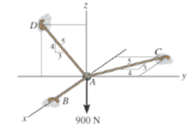
Chapter 3.4, Problem 8FP
Determine the tension developed in cables AB, AC, and AD.
Expert Solution & Answer
Want to see the full answer?
Check out a sample textbook solution
Students have asked these similar questions
(I) [40 Points] Using centered finite difference approximations as done in class, solve the equation for O:
d20
dx²
+ 0.010+ Q=0
subject to the boundary conditions shown in the stencil below. Do this for two values of Q: (a) Q = 0.3,
and (b) Q= √(0.5 + 2x)e-sinx (cos(5x)+x-0.5√1.006-x| + e −43*|1+.001+x* | * sin (1.5 − x) +
(cosx+0.001 + ex-1250+ sin (1-0.9x)|) * x - 4.68x4. For Case (a) (that is, Q = 0.3), use the stencil in Fig.
1. For Case (b), calculate with both the stencils in Fig. 1 and Fig 2. For all the three cases, show a table as
well as a plot of O versus x. Discuss your results. Use MATLAB and hand in the MATLAB codes.
1
0=0
x=0
2
3
4
0=1
x=1
Fig 1
1 2 3 4 5 6 7 8 9 10
11
0=0
x=0
0=1
x=1
Fig 2
Fig 2
(II) [60 Points] Using centered finite difference approximation as done in class, solve the equation:
020 020
+
მx2 მy2
+0.0150+Q=0
subject to the boundary conditions shown in the stencils below. Do this for two values of Q: (a) Q = 0.3,
and (b) Q = 10.5x² + 1.26 * 1.5 x 0.002 0.008. For Case (a) (that is, Q = 0.3) use Fig 3. For Case (b),
use both Fig. 3 and Fig 4. For all the three cases, show a table as well as the contour plots of versus
(x, y), and the (x, y) heat flux values at all the nodes on the boundaries x = 1 and y = 1. Discuss your
results. Use MATLAB and hand in the MATLAB codes. (Note that the domain is (x, y)e[0,1] x [0,1].)
0=0
0=0
4
8
12
16
10
Ꮎ0
15
25
9
14
19
24
3
11
15
0=0
8-0
0=0
3
8
13
18
23
2
6
сл
5
0=0
10
14
6
12
17
22
1
6
11
16
21
13
e=0
Fig 3
Fig 4
Textbook: Numerical Methods for Engineers, Steven C. Chapra and Raymond P. Canale, McGraw-Hill, Eighth
Edition (2021).
Ship construction question. Sketch and describe the forward arrangements of a ship. Include componets of the structure and a explanation of each part/ term.
Ive attached a general fore end arrangement. Simplfy construction and give a brief describion of the terms.
Chapter 3 Solutions
EP MODIFIED MASTERING ENGINEERING WITH
Ch. 3.3 - In each case, draw a free-body diagram of the ring...Ch. 3.3 - Write the two equations of equilibrium, Fx = 0 and...Ch. 3.3 - The crate has a weight of 550 lb. Determine the...Ch. 3.3 - The beam has a weight of 700 lb. Determine the...Ch. 3.3 - If the 5-kg block is suspended from the pulley B...Ch. 3.3 - The block has a mass of 5 kg and rests on the...Ch. 3.3 - If the mass of cylinder C is 40 kg, determine the...Ch. 3.3 - Determine the tension in cables AB, BC, and CD,...Ch. 3.3 - The members of a truss are pin connected at joint...Ch. 3.3 - The members of a truss are pin connected at joint...
Ch. 3.3 - Determine the magnitude and direction of F so...Ch. 3.3 - The bearing consists of rollers, symmetrically...Ch. 3.3 - The members of a truss are connected to the gusset...Ch. 3.3 - The gusset plate is subjected to the forces of...Ch. 3.3 - The man attempts to pull down the tree using the...Ch. 3.3 - The cords ABC and BD can each support a maximum...Ch. 3.3 - Determine the maximum force F that can be...Ch. 3.3 - The block has a weight of 20 lb and is being...Ch. 3.3 - Determine the maximum weight W of the block that...Ch. 3.3 - The lift sling is used to hoist a container having...Ch. 3.3 - A nuclear-reactor vessel has a weight of 500(103)...Ch. 3.3 - Determine the stretch in each spring for...Ch. 3.3 - The unstretched length of spring AB is 3 m. If the...Ch. 3.3 - Determine the mass of each of the two cylinders if...Ch. 3.3 - Determine the stiffness kT of the single spring...Ch. 3.3 - If the spring DB has an unstretched length of 2 m....Ch. 3.3 - Determine the unstretched length of DB to hold the...Ch. 3.3 - A vertical force P = 10 lb is applied to the ends...Ch. 3.3 - Determine the unstretched length of spring AC if a...Ch. 3.3 - The springs BA and BC each have a stiffness of 500...Ch. 3.3 - The springs BA and BC each nave a stiffness of 500...Ch. 3.3 - Determine the distances x and y for equilibrium if...Ch. 3.3 - Determine the magnitude of F1 and the distance y...Ch. 3.3 - The 30-kg pipe is supported at A by a system of...Ch. 3.3 - Each cord can sustain a maximum tension of 500 N....Ch. 3.3 - The streetlights A and B are suspended from the...Ch. 3.3 - Determine the tension developed in each cord...Ch. 3.3 - Prob. 30PCh. 3.3 - Prob. 31PCh. 3.3 - Prob. 32PCh. 3.3 - The lamp has a weight of 15 lb and is supported by...Ch. 3.3 - Each cord can sustain a maximum tension of 20 lb....Ch. 3.3 - Prob. 35PCh. 3.3 - Prob. 36PCh. 3.3 - Prob. 37PCh. 3.3 - Prob. 38PCh. 3.3 - The ball D has a mass of 20 kg. If a force of F =...Ch. 3.3 - The 200-lb uniform container is suspended by means...Ch. 3.3 - The single elastic cord ABC is used to support the...Ch. 3.3 - A scale is constructed with a 4-ft-long cord and...Ch. 3.3 - The concrete wall panel is hoisted into position...Ch. 3.3 - Prob. 2CPCh. 3.3 - Prob. 3CPCh. 3.3 - Prob. 4CPCh. 3.4 - Determine the magnitude of forces F1, F2, F3, so...Ch. 3.4 - Determine the tension developed in cables AB, AC,...Ch. 3.4 - Prob. 9FPCh. 3.4 - Prob. 10FPCh. 3.4 - Prob. 11FPCh. 3.4 - The three cables are used to support the 40-kg...Ch. 3.4 - Determine the magnitudes of F1, F2, and F3 for...Ch. 3.4 - If the bucket and its contents have a total weight...Ch. 3.4 - Determine the stretch in each of die two springs...Ch. 3.4 - Prob. 47PCh. 3.4 - Determine the tension in the cables in order to...Ch. 3.4 - Determine the maximum mass of the crate so that...Ch. 3.4 - Determine the force in each cable if F = 500 lb.Ch. 3.4 - Prob. 51PCh. 3.4 - Determine the tens on developed in cables AB and...Ch. 3.4 - If the tension developed in each cable cannot...Ch. 3.4 - Prob. 54PCh. 3.4 - Determine the maximum weight of the crate that can...Ch. 3.4 - The 25 kg flowerpot is supported at A by the three...Ch. 3.4 - If each cord can sustain a maximum tension of 50 N...Ch. 3.4 - Determine the tension developed m the three cables...Ch. 3.4 - Determine the tension developed in the three...Ch. 3.4 - Prob. 60PCh. 3.4 - Prob. 61PCh. 3.4 - If the maximum force in each rod con not exceed...Ch. 3.4 - Prob. 63PCh. 3.4 - If cable AD is tightened by a turnbuckle and...Ch. 3.4 - Prob. 65PCh. 3.4 - Prob. 66PCh. 3.4 - Determine the maximum weight of the crate so that...Ch. 3.4 - The pipe is held in place by the vise. If the bolt...Ch. 3.4 - Prob. 2RPCh. 3.4 - Prob. 3RPCh. 3.4 - Prob. 4RPCh. 3.4 - Prob. 5RPCh. 3.4 - Prob. 6RPCh. 3.4 - Determine the force in each cable needed to...Ch. 3.4 - If cable AB is subjected to a tension of 700 N,...
Knowledge Booster


Learn more about
Need a deep-dive on the concept behind this application? Look no further. Learn more about this topic, mechanical-engineering and related others by exploring similar questions and additional content below.Similar questions
- Problem 1 Consider R has a functional relationship with variables in the form R = K xq xx using show that n ✓ - (OR 1.) = i=1 2 Их Ux2 Ихэ 2 (177)² = ² (1)² + b² (12)² + c² (1)² 2 UR R x2 x3arrow_forward4. Figure 3 shows a crank loaded by a force F = 1000 N and Mx = 40 Nm. a. Draw a free-body diagram of arm 2 showing the values of all forces, moments, and torques that act due to force F. Label the directions of the coordinate axes on this diagram. b. Draw a free-body diagram of arm 2 showing the values of all forces, moments, and torques that act due to moment Mr. Label the directions of the coordinate axes on this diagram. Draw a free body diagram of the wall plane showing all the forces, torques, and moments acting there. d. Locate a stress element on the top surface of the shaft at A and calculate all the stress components that act upon this element. e. Determine the principal stresses and maximum shear stresses at this point at A.arrow_forward3. Given a heat treated 6061 aluminum, solid, elliptical column with 200 mm length, 200 N concentric load, and a safety factor of 1.2, design a suitable column if its boundary conditions are fixed-free and the ratio of major to minor axis is 2.5:1. (Use AISC recommended values and round the ellipse dimensions so that both axes are whole millimeters in the correct 2.5:1 ratio.)arrow_forward
- 1. A simply supported shaft is shown in Figure 1 with w₁ = 25 N/cm and M = 20 N cm. Use singularity functions to determine the reactions at the supports. Assume El = 1000 kN cm². Wo M 0 10 20 30 40 50 60 70 80 90 100 110 cm Figure 1 - Problem 1arrow_forwardPlease AnswerSteam enters a nozzle at 400°C and 800 kPa with a velocity of 10 m/s and leaves at 375°C and 400 kPa while losing heat at a rate of 26.5 kW. For an inlet area of 800 cm2, determine the velocity and the volume flow rate of the steam at the nozzle exit. Use steam tables. The velocity of the steam at the nozzle exit is m/s. The volume flow rate of the steam at the nozzle exit is m3/s.arrow_forward2. A support hook was formed from a rectangular bar. Find the stresses at the inner and outer surfaces at sections just above and just below O-B. -210 mm 120 mm 160 mm 400 N B thickness 8 mm = Figure 2 - Problem 2arrow_forward
- Steam flows steadily through a turbine at a rate of 45,000 lbm/h, entering at 1000 psia and 900°F and leaving at 5 psia as saturated vapor. If the power generated by the turbine is 4.1 MW, determine the rate of heat loss from the steam. The enthalpies are h1 = 1448.6 Btu/lbm and h2 = 1130.7 Btu/lbm. The rate of heat loss from the steam is Btu/s.arrow_forwardThe A/D converter wit the specifications listed below is planned to be used in an environment in which the A/D converter temperature may change by ± 10 °C. Estimate the contributions of conversion and quantization errors to the uncertainty in the digital representation of an analog voltage by the converter. FSO N Linearity error Temperature drift error Analog to Digital (A/D) Converter 0-10 V 12 bits ± 3 bits 1 bit/5 °Carrow_forward6-13. A smooth tube in the form of a circle of radius r rotates in its vertical plane with a constant angular velocity w. The position of a particle of mass m that slides inside the tube is given by the relative coordinate p. Find the differential equation for . e О E g ω Figure P6-13arrow_forward
- Problem 2 Consider the power drawn by a resistance load in a DC circuit. The power is calculated as P = VI or P = 1²R. It is given that the normalized uncertainty or % percentage uncertainty in measurements of I, R, and V are the same. Find the uncertainty in P using the two different expressions for power. Is the uncertainty using the two methods the same? If not, WHY, explain?arrow_forwardA piston–cylinder device contains 3 kg of nitrogen initially at 100 kPa and 25°C. Nitrogen is now compressed slowly in a polytropic process during which PV1.3 = constant until the volume is reduced by one-half. Determine the work done and the heat transfer for this process. The gas constant of N2 is R = 0.2968 kPa·m3/kg·K. The cv value of N2 at the anticipated average temperature of 350 K is 0.744 kJ/kg·K (Table A-2b). The work done for this process is kJ. The heat transfer for this process is kJ.arrow_forwardI tried solving this one but I have no idea where I went wrong can you please help me out with this?arrow_forward
arrow_back_ios
SEE MORE QUESTIONS
arrow_forward_ios
Recommended textbooks for you
 International Edition---engineering Mechanics: St...Mechanical EngineeringISBN:9781305501607Author:Andrew Pytel And Jaan KiusalaasPublisher:CENGAGE L
International Edition---engineering Mechanics: St...
Mechanical Engineering
ISBN:9781305501607
Author:Andrew Pytel And Jaan Kiusalaas
Publisher:CENGAGE L
Engineering Basics - Statics & Forces in Equilibrium; Author: Solid Solutions - Professional Design Solutions;https://www.youtube.com/watch?v=dQBvQ2hJZFg;License: Standard YouTube License, CC-BY