ENGINEERING MECHANICS:STATICS AND DYNAMI
14th Edition
ISBN: 9780135698921
Author: HIBBELER
Publisher: PEARSON
expand_more
expand_more
format_list_bulleted
Concept explainers
Videos
Textbook Question
Chapter 3.4, Problem 1RP
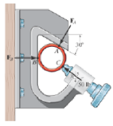
The pipe is held in place by the vise. If the bolt exerts a force of 50 lb on the pipe in the direction shown, determine the forces FA and FB that the smooth contacts at A and B exert on the pipe.
Expert Solution & Answer
Want to see the full answer?
Check out a sample textbook solution
Students have asked these similar questions
=
The steel curved bar shown has rectangular cross-section with a radial height h = 6 mm and thickness b = 4mm. The
radius of the centroidal axis is R = 80 mm. A force P = 10 N is applied as shown. Assume the steel modulus of
207,000 MPa and G = 79.3(103) MPa, repectively.
elasticity and shear modulus E =
Find the vertical deflection at point B. Use Castigliano's method for a curved flexural member and since R/h > 10,
neglect the effect of shear and axial load, thereby assuming that deflection is due to merely the bending moment.
Note the inner and outer radii of the curves bar are:
r = 80 + ½ (6) = 83 mm, r₁ = 80 − ½ (6) = 77 mm
2
2
Sπ/2 sin² 0 d = √π/² cos² 0 d0 =
Π
0
4
大
C
R
B
P
The steel eyebolt shown in the figure is loaded with a force F = 75 lb. The eyebolt is formed from round wire of
diameter d = 0.25 in to a radius R₁ = 0.50 in in the eye and at the shank.
Estimate the stresses at the inner and outer surfaces at section A-A.
Notice at the section A-A:
r₁ = 0.5 in, ro
= 0.75 in
rc
=
0.5 + 0.125 = 0.625 in
Ri
200
F
FA
I have the fallowing question and solution from a reeds naval arc book. Im just confused as to where this answer came from and the formulas used. Wondering if i could have this answer/ solution broken down and explained in detail.
A ship of 7000 tonne displacement has a waterplane areaof 1500 m2. In passing from sea water into river water of1005 kg/m3 there is an increase in draught of 10 cm. Find the Idensity of the sea water.
picture of the "answer" is attached
Chapter 3 Solutions
ENGINEERING MECHANICS:STATICS AND DYNAMI
Ch. 3.3 - In each case, draw a free-body diagram of the ring...Ch. 3.3 - Write the two equations of equilibrium, Fx = 0 and...Ch. 3.3 - The crate has a weight of 550 lb. Determine the...Ch. 3.3 - The beam has a weight of 700 lb. Determine the...Ch. 3.3 - If the 5-kg block is suspended from the pulley B...Ch. 3.3 - The block has a mass of 5 kg and rests on the...Ch. 3.3 - If the mass of cylinder C is 40 kg, determine the...Ch. 3.3 - Determine the tension in cables AB, BC, and CD,...Ch. 3.3 - The members of a truss are pin connected at joint...Ch. 3.3 - The members of a truss are pin connected at joint...
Ch. 3.3 - Determine the magnitude and direction of F so...Ch. 3.3 - The bearing consists of rollers, symmetrically...Ch. 3.3 - The members of a truss are connected to the gusset...Ch. 3.3 - The gusset plate is subjected to the forces of...Ch. 3.3 - The man attempts to pull down the tree using the...Ch. 3.3 - The cords ABC and BD can each support a maximum...Ch. 3.3 - Determine the maximum force F that can be...Ch. 3.3 - The block has a weight of 20 lb and is being...Ch. 3.3 - Determine the maximum weight W of the block that...Ch. 3.3 - The lift sling is used to hoist a container having...Ch. 3.3 - A nuclear-reactor vessel has a weight of 500(103)...Ch. 3.3 - Determine the stretch in each spring for...Ch. 3.3 - The unstretched length of spring AB is 3 m. If the...Ch. 3.3 - Determine the mass of each of the two cylinders if...Ch. 3.3 - Determine the stiffness kT of the single spring...Ch. 3.3 - If the spring DB has an unstretched length of 2 m....Ch. 3.3 - Determine the unstretched length of DB to hold the...Ch. 3.3 - A vertical force P = 10 lb is applied to the ends...Ch. 3.3 - Determine the unstretched length of spring AC if a...Ch. 3.3 - The springs BA and BC each have a stiffness of 500...Ch. 3.3 - The springs BA and BC each nave a stiffness of 500...Ch. 3.3 - Determine the distances x and y for equilibrium if...Ch. 3.3 - Determine the magnitude of F1 and the distance y...Ch. 3.3 - The 30-kg pipe is supported at A by a system of...Ch. 3.3 - Each cord can sustain a maximum tension of 500 N....Ch. 3.3 - The streetlights A and B are suspended from the...Ch. 3.3 - Determine the tension developed in each cord...Ch. 3.3 - Prob. 30PCh. 3.3 - Prob. 31PCh. 3.3 - Prob. 32PCh. 3.3 - The lamp has a weight of 15 lb and is supported by...Ch. 3.3 - Each cord can sustain a maximum tension of 20 lb....Ch. 3.3 - Prob. 35PCh. 3.3 - Prob. 36PCh. 3.3 - Prob. 37PCh. 3.3 - Prob. 38PCh. 3.3 - The ball D has a mass of 20 kg. If a force of F =...Ch. 3.3 - The 200-lb uniform container is suspended by means...Ch. 3.3 - The single elastic cord ABC is used to support the...Ch. 3.3 - A scale is constructed with a 4-ft-long cord and...Ch. 3.3 - The concrete wall panel is hoisted into position...Ch. 3.3 - Prob. 2CPCh. 3.3 - Prob. 3CPCh. 3.3 - Prob. 4CPCh. 3.4 - Determine the magnitude of forces F1, F2, F3, so...Ch. 3.4 - Determine the tension developed in cables AB, AC,...Ch. 3.4 - Prob. 9FPCh. 3.4 - Prob. 10FPCh. 3.4 - Prob. 11FPCh. 3.4 - The three cables are used to support the 40-kg...Ch. 3.4 - Determine the magnitudes of F1, F2, and F3 for...Ch. 3.4 - If the bucket and its contents have a total weight...Ch. 3.4 - Determine the stretch in each of die two springs...Ch. 3.4 - Prob. 47PCh. 3.4 - Determine the tension in the cables in order to...Ch. 3.4 - Determine the maximum mass of the crate so that...Ch. 3.4 - Determine the force in each cable if F = 500 lb.Ch. 3.4 - Prob. 51PCh. 3.4 - Determine the tens on developed in cables AB and...Ch. 3.4 - If the tension developed in each cable cannot...Ch. 3.4 - Prob. 54PCh. 3.4 - Determine the maximum weight of the crate that can...Ch. 3.4 - The 25 kg flowerpot is supported at A by the three...Ch. 3.4 - If each cord can sustain a maximum tension of 50 N...Ch. 3.4 - Determine the tension developed m the three cables...Ch. 3.4 - Determine the tension developed in the three...Ch. 3.4 - Prob. 60PCh. 3.4 - Prob. 61PCh. 3.4 - If the maximum force in each rod con not exceed...Ch. 3.4 - Prob. 63PCh. 3.4 - If cable AD is tightened by a turnbuckle and...Ch. 3.4 - Prob. 65PCh. 3.4 - Prob. 66PCh. 3.4 - Determine the maximum weight of the crate so that...Ch. 3.4 - The pipe is held in place by the vise. If the bolt...Ch. 3.4 - Prob. 2RPCh. 3.4 - Prob. 3RPCh. 3.4 - Prob. 4RPCh. 3.4 - Prob. 5RPCh. 3.4 - Prob. 6RPCh. 3.4 - Determine the force in each cable needed to...Ch. 3.4 - If cable AB is subjected to a tension of 700 N,...
Knowledge Booster


Learn more about
Need a deep-dive on the concept behind this application? Look no further. Learn more about this topic, mechanical-engineering and related others by exploring similar questions and additional content below.Similar questions
- Problem A2 long steel tube has a rectangular cross-section with outer dimensions of 20 x 20 mm and a uniform wall thickness of 2. The tube is twisted along its length with torque, T. The tube material is 1045 CD steel with shear yield strength of S,, =315 MPa. Assume shear modulus, G = 79.3GPa. (a) Estimate the maximum torque that can be applied without yielding (b) Estimate the torque required to produce 5 degrees total angle of twist over the length of the tube. (c) What is the maximum torque that can be applied without yielding, if a solid rectangular shaft with dimensions of 20 x 20 is used? You may use the exact solution.arrow_forwardA simply supported beam is loaded as shown. Considering symmetry, the reactions at supports A and B are R₁ = R₂ = wa 2 Using the singularity method, determine the shear force V along the length of the beam as a function of distance x from the support A. A B Ir. 2a За W C R₁₂ x 2. Using the singularity method, determine the bending M along the length of the beam as a function of distance x, from the support A. 3. Using the singularity method, determine the beam slope and deflection along the length of the beam as a function of the distance x, from the support A. Assume the material modulus of elasticity, E and the moment of inertia of the beam cross-section, I are given.arrow_forwardA steel tube, 2 m long, has a rectangular cross-section with outer dimensions of 20 × 30 mm and a uniform wall thickness of 1 mm. The tube is twisted along its length with torque, T. The tube material is 1018 CD steel with shear yield strength of Ssy =185 MPa. Assume shear modulus, G = 79.3GPa. (a) Estimate the maximum torque that can be applied without yielding.- (b) Estimate the torque required to produce 3 degrees total angle of twist over the length of the tube. (c) What is the maximum torque that can be applied without yielding, if a solid rectangular shaft with dimensions of 20 x 30 mm is used? You may use the exact solution:arrow_forward
- |The typical cruising altitude of a commercial jet airliner is 10,700 m above sea level where the local atmospheric temperature is 219 K, and the pressure is 0.25 bar. The aircraft utilizes a cold air-standard Brayton cycle as shown with a volume flow rate of 1450 m³/s. The compressor pressure ratio is 50, and the maximum cycle temperature is 1700 K. The compressor and turbine isentropic efficiencies are 90%. Neglect kinetic and potential energy effects in this problem. Assume constant specific heats with k=1.4, Ra=0.287 kJ/kg- K, Cp=1.0045 kJ/kg-K, and cv = 0.7175 kJ/kg-K. a) Draw a T-s diagram for this cycle on the diagram provided. b) Fill in the table below with the missing information. T[K] Heat exchanger Heat exchanger State P [bar] 1 0.25 2s 2 3 4s 4 Turbine c) (5pts) Determine the inlet air density in [kg/m³] (at state 1), and the system mass flowrate in [kg/s]. d) (10pts) Determine the net power developed in [MW]. Be sure to draw each component you are analyzing, define the…arrow_forwardOn the axis provide, draw a corresponding T-s diagram for the Brayton cycle shown given the following information: iv. V. vi. Compressor 1 is reversible, but Compressor 2 and the turbine are irreversible. The pressure drops through the regenerator are combustors are negligible. The pressures at state (1) and state (10) are equal to the atmospheric pressure. T 8 Regenerator fmm mmm Qin Combustor Compressor Compressor Turbine W cycle Intercooler mm Courarrow_forwardFor parts a) through e), consider the two power cycles shown in the diagram at the right, Cycle A: 1-2-3-4-1, and Cycle B: 1-2-3-4-1. a) What type of power cycles are shown? b) Which of cycles has a higher efficiency? c) Which of the cycles has a higher work output? d) For either cycle, would increasing the maximum cycle temperature (3) increase or decrease the efficiency? Cycle A: 1-2-3-4-1 3 3 Cycle B: 1-2-3-4-1 1 e) For either cycle, would decreasing the minimum cycle temperature (1) increase or decrease the efficiency? f) On the axis provide, draw a corresponding T-s diagram for the Rankine cycle shown given the following information: i. All turbines and pumps in the system are irreversible. ii. 111. The turbine inlet conditions (states 1 and 2) are superheated, while the 2nd stage turbine outlet is a saturated mixture. The condenser outlet state (4) and the CFWH outlet state (7) are saturated liquid. 2 Steam generator Condenser www Closed feedwater heater (1-y) T Pump Trap 8 (y) Sarrow_forward
- Problem 4 A glass sphere with a 30 mm diameter is pressed against a flat carbon steel plate with a force of 5 N. Assume. For glass: E = 46.2 GPa, -0.245 and for steel E, 207 GPa, (a) Determine the radius of the contact surface. -0.292 (4 (b) Determine the maximum pressure at the contact surface. (4 (c) Calculate the principal stresses d., and a, in the glass sphere at the depth=0.037 mm. (d) Maximum shear stress in the glass sphere at the depth: 0.037 mm. (t (4 (e) Draw the Mohr circles for the stresses and show the point corresponding to the maximum shear stress. (3arrow_forwardSteam is the working fluid in the vapor power cycle with reheat shown in the figure. The mass flow rate is 0.5 kg/s, and the turbines and pump operate isentropically. The temperature at the inlet of both turbine stages (i.e. states 1 and 3) is 400 °C The condenser outlet is saturated liquid. 1. Fill in the table below with the missing information. Reheat section High- pressure turbine State P [bar] h [kJ/kg] s [kJ/kg-K] x [-] Steam generator 1 140 Condenser Pump 2 40 5 3 4 4 5 6 2.Draw a T-s diagram for this cycle on the diagram provided 3. Determine the net power output of this cycle in [kW]. Be sure to draw the component(s) you are analyzing, define the system, and apply conservation of energy in the space below. 4.Determine the total heat transferred into the system in [kW]. Be sure to draw the component you are analyzing, define the system, and apply conservation of energy in the space bel 5.Determine the cycle efficiency. Low-pressure turbinearrow_forwardCalculate the moment of F about axis AB. Express the moment as a Cartesian vector, and then state its magnitude. The radii of the curved sections are all 0.5 m. F acts on the bottom center of the hook, and the hook lies in the yz plane.arrow_forward
- Determine the moment created by the force FAB about the point E. Assume FAB = 800 lbs. Express your answer as a Cartesian vector (ME) and state the magnitude of the moment.arrow_forwardDetermine the couple moment acting on the beam. Express it as a Cartesian vector.arrow_forwardDetermine Cartesian vector expressions for reaction forces at A and B i.e. determine FA and FB.arrow_forward
arrow_back_ios
SEE MORE QUESTIONS
arrow_forward_ios
Recommended textbooks for you
 International Edition---engineering Mechanics: St...Mechanical EngineeringISBN:9781305501607Author:Andrew Pytel And Jaan KiusalaasPublisher:CENGAGE L
International Edition---engineering Mechanics: St...
Mechanical Engineering
ISBN:9781305501607
Author:Andrew Pytel And Jaan Kiusalaas
Publisher:CENGAGE L
Engineering Basics - Statics & Forces in Equilibrium; Author: Solid Solutions - Professional Design Solutions;https://www.youtube.com/watch?v=dQBvQ2hJZFg;License: Standard YouTube License, CC-BY