Electricity for Refrigeration, Heating, and Air Conditioning (MindTap Course List)
10th Edition
ISBN: 9781337399128
Author: Russell E. Smith
Publisher: Cengage Learning
expand_more
expand_more
format_list_bulleted
Concept explainers
Videos
Textbook Question
Chapter 3, Problem 1RQ
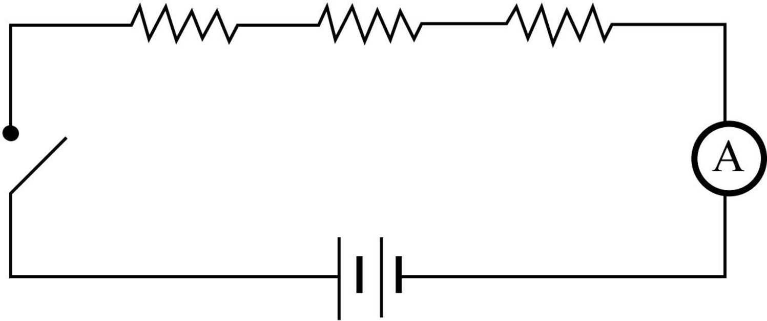
What is a series circuit?
Expert Solution & Answer
To determine
The definition of a series circuit.
Explanation of Solution
A circuit in which only one path of flow of electricity is present and the components presents in the circuit are wired with end to end connection is called series circuit. In a series circuit the current leaves from first component must enter to the second component, because the component present in series circuit is connected with end to end. The current through each component (Resistor’s) in a series circuit is same.
The below figure represents schematic diagram of a series circuit.
Want to see more full solutions like this?
Subscribe now to access step-by-step solutions to millions of textbook problems written by subject matter experts!
Students have asked these similar questions
USE MATLAB ONLY
Turbomachienery .
GIven:
vx = 185 m/s, flow angle = 60 degrees, R = 0.5, U = 150 m/s, b2 = -a3, a2 = -b3
Find: velocity triangle , a. magnitude of abs vel leaving rotor (m/s) b. flow absolute angles (a1, a2, a3) 3. flow rel angles (b2, b3) d. specific work done e. use code to draw vel. diagram
Use this code for plot
% plots Velocity Tri. in Ch4
function plotveltri(al1,al2,al3,b2,b3)
S1L = [0 1];
V1x = [0 0];
V1s = [0 1*tand(al3)];
S2L = [2 3];
V2x = [0 0];
V2s = [0 1*tand(al2)];
W2s = [0 1*tand(b2)];
U2x = [3 3];
U2y = [1*tand(b2) 1*tand(al2)];
S3L = [4 5];
V3x = [0 0];
V3r = [0 1*tand(al3)];
W3r = [0 1*tand(b3)];
U3x = [5 5];
U3y = [1*tand(b3) 1*tand(al3)];
plot(S1L,V1x,'k',S1L,V1s,'r',...
S2L,V2x,'k',S2L,V2s,'r',S2L,W2s,'b',U2x,U2y,'g',...
S3L,V3x,'k',S3L,V3r,'r',S3L,W3r,'b',U3x,U3y,'g',......
'LineWidth',2,'MarkerSize',10),...
axis([-1 6 -4 4]), ...
title('Velocity Triangle'), ...
xlabel('x'),yl
The wall of a furnace has a thickness of 5 cm and thermal conductivity
of 0.7 W/m-°C. The inside surface is heated by convection with a hot
gas at 402°C and a heat transfer coefficient of 37 W/m²-°C. The
outside surface has an emissivity of 0.8 and is exposed to air at 27°C
with a heat transfer coefficient of 20 W/m²-ºC. Assume that the
furnace is inside a large room with walls, floor and ceiling at 27°C.
Show the thermal circuit and determine the heat flux through the
furnace wall.
h₁
T₁
k
-L
T.
sur
ho
E
Turbomachienery .
GIven:
vx = 185 m/s, flow angle = 60 degrees, R = 0.5, U = 150 m/s, b2 = -a3, a2 = -b3
Find: velocity triangle , a. magnitude of abs vel leaving rotor (m/s) b. flow absolute angles (a1, a2, a3) 3. flow rel angles (b2, b3) d. specific work done e. use code to draw vel. diagram
Use this code for plot
% plots Velocity Tri. in Ch4
function plotveltri(al1,al2,al3,b2,b3)
S1L = [0 1];
V1x = [0 0];
V1s = [0 1*tand(al3)];
S2L = [2 3];
V2x = [0 0];
V2s = [0 1*tand(al2)];
W2s = [0 1*tand(b2)];
U2x = [3 3];
U2y = [1*tand(b2) 1*tand(al2)];
S3L = [4 5];
V3x = [0 0];
V3r = [0 1*tand(al3)];
W3r = [0 1*tand(b3)];
U3x = [5 5];
U3y = [1*tand(b3) 1*tand(al3)];
plot(S1L,V1x,'k',S1L,V1s,'r',...
S2L,V2x,'k',S2L,V2s,'r',S2L,W2s,'b',U2x,U2y,'g',...
S3L,V3x,'k',S3L,V3r,'r',S3L,W3r,'b',U3x,U3y,'g',......
'LineWidth',2,'MarkerSize',10),...
axis([-1 6 -4 4]), ...
title('Velocity Triangle'), ...
xlabel('x'),ylabel('y'), grid
Chapter 3 Solutions
Electricity for Refrigeration, Heating, and Air Conditioning (MindTap Course List)
Ch. 3 - What is a series circuit?Ch. 3 - What is a control circuit?Ch. 3 - Safety devices in an electrical circuit are...Ch. 3 - How are series circuits used in air-conditioning...Ch. 3 - Why are series circuits used for most control...Ch. 3 - The current draw in a series circuit is _____. a....Ch. 3 - The voltage drop of a series circuit is _____. a....Ch. 3 - How would switches used as safety devices be...Ch. 3 - Draw a series circuit with a thermostat, a...Ch. 3 - Two identical 115-volt light bulbs connected in...
Ch. 3 - Prob. 11RQCh. 3 - Prob. 12RQCh. 3 - Parallel circuits are used in the air-conditioning...Ch. 3 - Why are parallel circuits used in the...Ch. 3 - Prob. 15RQCh. 3 - Prob. 16RQCh. 3 - If two 115-volt loads were connected in parallel...Ch. 3 - What is a series-parallel circuit?Ch. 3 - Why are series-parallel control circuits important...Ch. 3 - Draw a series-parallel circuit with one switch...Ch. 3 - What is the resistance of a parallel circuit with...Ch. 3 - What is the resistance of a parallel circuit with...Ch. 3 - What is the total ampere draw of a parallel...Ch. 3 - What is the voltage of a series circuit with four...Ch. 3 - What is the resistance of a series circuit with...
Knowledge Booster


Learn more about
Need a deep-dive on the concept behind this application? Look no further. Learn more about this topic, mechanical-engineering and related others by exploring similar questions and additional content below.Similar questions
- To save fuel during the heating season it is suggested that glass windows be covered at night with a 1.2 cm layer of polystyrene. Estimate the percent savings in energy and discuss the feasibility of this idea. Show the thermal circuit with and without the insulation panel. Consider a typical case of 0.2 cm thick window glass with inside and outside heat transfer coefficients of 6 and 32 W/m²-ºC. Lg←←Lp h T₁ T。 g kp insulation panelarrow_forwardA plate of thickness L and thermal conductivity k is exposed to a fluid at temperature T1 with a heat transfer coefficient h, on one side and T2 and h₂ on the other side. Determine the one-dimensional temperature distribution in the plate. Assume steady state and constant conductivity. L h h T%2 k Tx1 0xarrow_forwardDetermine the heater capacity needed to maintain the inside temperature of a laboratory chamber at 38°C when placed in a room at 21°C. The chamber is cubical with each side measuring 35 cm. The walls are 1.2 cm thick and are made of polystyrene. The inside and outside heat transfer coefficients are 5 and 22 W/m²-°C.arrow_forward
- (a) Refer to the above figure .What kind of controller is it ? (b) simplify the block diagramto derive the closed loop transfer function of the system. (C) What are the assumptions thatare needed to make to findthe controller gain ? What arethe value of Kp , Ti and Td ?arrow_forwardLonsider a regenerative gas turbine power plant with two stages of compression and two stages of expansion. The compressor pressure ratio of the compressor is 3. Air enters each stage of compressor at 290 K and esch stage of turbine at 1400 K. The regetierator has an effectiveness of 100%, Determine (a) The enthalpy at stage#2 in KJ/kg (b) The enthalpy at stage in KJ/kg" (c) The cathalpy at stager in KJ/kg* (d) The enthalpy at stage#10 in KJ/kg (c) The mass flow rate of air needed to develop a net power output of 50 MW *For all final answers please enter the integer part only, (ie 1234) and do not include the decimal part and the decimal point No rounding in your calculationarrow_forwardConsider a regenerative gas turbine power plant with two stages of compression and two stages of expansion. The compressor pressure ratio of the compressor is 3. Air enters each stage of compressor at 290 K and each stage of turbine at 1400 K. The regenerator has an effectiveness of 100%. Determine (a) The enthalpy at stage#2 in KJ/kg⭑ (b) The enthalpy at stage#6 in KJ/kg* (c) The enthalpy at stage#9 in KJ/kg (d) The enthalpy at stage#10 in KJ/kg (e)The mass flow rate of air needed to develop a net power output of 50 MW* *For all final answers please enter the integer part only, (ie 1234) and do not include the decimal part and the decimal point No rounding in your calculation. Compressor stage 1 Regenerator www HX ww 9 Combustor Reheat Intercooler ww Compressor stage 2 Turbine 1 combustor Turbine 2arrow_forward
- Design a proportional derivitivecontroller for a plant orsystemthat satisfies the following specifications : 1. is steady-state error is less than 2 % for a ramp input. 2.) Damping ratio (zeta) is greater than 0.7have determined the 3. Once youvalue of kp and kd, then plotthe response of the compensated(with controller) and uncompensated( without the controller, only the plantsystem using MATLAB.arrow_forwardExample 2 The particle has a mass of 0.5 kg and is confined to move along the smooth horizontal slot due to the rotation of the arm OA. Determine the force of the rod on the particle and the normal force of the slot on the particle when 0 = 30°. The rod is rotating with a constant angular velocity 2 rad/s. Assume the particle contacts only one side of the slot at any instant. B =2 rad/s 0.5 m 0.5(9.81)N r F 30° Narrow_forwardA gas turbine cycle has two stages of compression, with an intercooler between the stages. Air enters the first stage at 100 kPa, 300 K. The pressure efficiency of 82%. Air exits the intercooler at 330 K. Calculate the temperature at the exit of each compressor stage and the total specific work required.arrow_forward
- For problem 13, your answer should be the same as problem 12. Calculate the flow velocity and the heat transfer/area of the outer surfaces for both duct geometries to see the performance difference of the two designs.arrow_forwardOne end of a thin uniform rod of mass m and length 31 rests against a smooth vertical wall. The other end of the rod is attached by a string of length 1 to a fixed point O which is located a distance 21 from the wall. A horizontal force of magnitude F₁ is applied to the lower end of the rod as shown. Assuming the rod and the string remain in the same vertical plane perpendicular to the wall, find the angle 0 between the rod and the wall at the position of static equilibrium. Notes: This quiz is going to walk you through a sequence of steps to do this. It won't give you the answers, but it will hopefully get you to see how to approach problems like this so that you have a working reference/template in the future. This is actually a modified version of a problem from the textbook (6.3). Note that in that problem, is not actually given. It has been introduced for convenience as we move through solving the problem, and should not show up in the final answer. DO NOT DO PROBLEM 6.3. It is…arrow_forwardvarrow_forward
arrow_back_ios
SEE MORE QUESTIONS
arrow_forward_ios
Recommended textbooks for you
 Understanding Motor ControlsMechanical EngineeringISBN:9781337798686Author:Stephen L. HermanPublisher:Delmar Cengage Learning
 Automotive Technology: A Systems Approach (MindTa...Mechanical EngineeringISBN:9781133612315Author:Jack Erjavec, Rob ThompsonPublisher:Cengage Learning
 Electrical Transformers and Rotating MachinesMechanical EngineeringISBN:9781305494817Author:Stephen L. HermanPublisher:Cengage Learning
 Refrigeration and Air Conditioning Technology (Mi...Mechanical EngineeringISBN:9781305578296Author:John Tomczyk, Eugene Silberstein, Bill Whitman, Bill JohnsonPublisher:Cengage Learning
 Automotive TechnologyMechanical EngineeringISBN:9781337794213Author:ERJAVEC, Jack.Publisher:Cengage,
Understanding Motor Controls
Mechanical Engineering
ISBN:9781337798686
Author:Stephen L. Herman
Publisher:Delmar Cengage Learning
Automotive Technology: A Systems Approach (MindTa...
Mechanical Engineering
ISBN:9781133612315
Author:Jack Erjavec, Rob Thompson
Publisher:Cengage Learning
Electrical Transformers and Rotating Machines
Mechanical Engineering
ISBN:9781305494817
Author:Stephen L. Herman
Publisher:Cengage Learning
Refrigeration and Air Conditioning Technology (Mi...
Mechanical Engineering
ISBN:9781305578296
Author:John Tomczyk, Eugene Silberstein, Bill Whitman, Bill Johnson
Publisher:Cengage Learning
Automotive Technology
Mechanical Engineering
ISBN:9781337794213
Author:ERJAVEC, Jack.
Publisher:Cengage,
EVERYTHING on Axial Loading Normal Stress in 10 MINUTES - Mechanics of Materials; Author: Less Boring Lectures;https://www.youtube.com/watch?v=jQ-fNqZWrNg;License: Standard YouTube License, CC-BY