
Concept explainers
Videos
- 10. Show that for circular motion, force = mass * velocity squared/radius.
Show that the force of the circular motion is,
Answer to Problem 10MDP
The force of the circular motion is proved as
Explanation of Solution
Circular motion is defined as the movement of an object along a circular path. When an object is moved at constant speed, the velocity is changed due to its direction not because of its magnitude. This changing velocity shows that the object is accelerating. To obtain this accelerating there should be a force which is called as centripetal force.
The derivation of the force of the circular motion is as follows,
Consider a ball moving with the constant speed
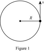
To derive the acceleration consider the initial velocity at
Now modify Figure 1 as shown in Figure 2.
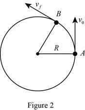
Use the similar triangles in Figure2, therefore it becomes as follows:
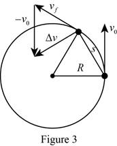
The acceleration is the rate of change of velocity.
Using similar triangle theorem,
The arc with the chord is,
Rearrange equation (3) to find
Rearrange equation (2) to find
Substitute equation (5) in equation (1) to obtain the expression of acceleration in terms of
Substitute
Write the expression for force.
Substitute equation (7) in (8) to obtain the expression force of the circular motion.
Here,
Therefore, the equation (9) shows the force of the circular motion.
Conclusion:
Thus, the force of the circular motion is proved as
Want to see more full solutions like this?
Chapter 3 Solutions
Thinking Like an Engineer: An Active Learning Approach (3rd Edition)
Additional Engineering Textbook Solutions
Web Development and Design Foundations with HTML5 (8th Edition)
Computer Science: An Overview (13th Edition) (What's New in Computer Science)
Java How to Program, Early Objects (11th Edition) (Deitel: How to Program)
Starting Out With Visual Basic (8th Edition)
Modern Database Management
Electric Circuits. (11th Edition)


- **Problem 8-45.** The man has a mass of 60 kg and the crate has a mass of 100 kg. If the coefficient of static friction between his shoes and the ground is \( \mu_s = 0.4 \) and between the crate and the ground is \( \mu_c = 0.3 \), determine if the man is able to move the crate using the rope-and-pulley system shown. **Diagram Explanation:** The diagram illustrates a scenario where a man is attempting to pull a crate using a rope-and-pulley system. The setup is as follows: - **Crate (C):** Positioned on the ground with a rope attached. - **Rope:** Connects the crate to a pulley system and extends to the man. - **Pulley on Tree:** The rope runs over a pulley mounted on a tree which redirects the rope. - **Angles:** - The rope between the crate and tree forms a \(30^\circ\) angle with the horizontal. - The rope between the tree and the man makes a \(45^\circ\) angle with the horizontal. - **Man (A):** Pulling on the rope with the intention of moving the crate. This arrangement tests the…arrow_forwardplease solve this problems follow what the question are asking to do please show me step by steparrow_forwardplease first write the line action find the forces and them solve the problem step by steparrow_forward
- please solve this problem what the problem are asking to solve please explain step by step and give me the correct answerarrow_forwardplease help me to solve this problem step by steparrow_forwardplease help me to solve this problem and determine the stress for each point i like to be explained step by step with the correct answerarrow_forward
- please solve this problem for me the best way that you can explained to solve please show me the step how to solvearrow_forwardplese solbe this problem and give the correct answer solve step by step find the forces and line actionarrow_forwardplease help me to solve this problems first write the line of action and them find the forces {fx=0: fy=0: mz=0: and them draw the shear and bending moment diagram. please explain step by steparrow_forward
- please solve this problem step by step like human and give correct answer step by steparrow_forwardPROBLEM 11: Determine the force, P, that must be exerted on the handles of the bolt cutter. (A) 7.5 N (B) 30.0 N (C) 52.5 N (D) 300 N (E) 325 N .B X 3 cm E 40 cm cm F = 1000 N 10 cm 3 cm boltarrow_forwardUsing the moment-area theorems, determine a) the rotation at A, b) the deflection at L/2, c) the deflection at L/4. (Hint: Use symmetry for Part a (θA= - θB, or θC=0), Use the rotation at A for Parts b and c. Note that all deformations in the scope of our topics are small deformation and for small θ, sinθ=θ).arrow_forward
 Elements Of ElectromagneticsMechanical EngineeringISBN:9780190698614Author:Sadiku, Matthew N. O.Publisher:Oxford University Press
 Mechanics of Materials (10th Edition)Mechanical EngineeringISBN:9780134319650Author:Russell C. HibbelerPublisher:PEARSON
 Thermodynamics: An Engineering ApproachMechanical EngineeringISBN:9781259822674Author:Yunus A. Cengel Dr., Michael A. BolesPublisher:McGraw-Hill Education
 Control Systems EngineeringMechanical EngineeringISBN:9781118170519Author:Norman S. NisePublisher:WILEY
 Mechanics of Materials (MindTap Course List)Mechanical EngineeringISBN:9781337093347Author:Barry J. Goodno, James M. GerePublisher:Cengage Learning
 Engineering Mechanics: StaticsMechanical EngineeringISBN:9781118807330Author:James L. Meriam, L. G. Kraige, J. N. BoltonPublisher:WILEY