
Vector Mechanics for Engineers: Statics
12th Edition
ISBN: 9781259977268
Author: Ferdinand P. Beer, E. Russell Johnston Jr., David Mazurek
Publisher: McGraw-Hill Education
expand_more
expand_more
format_list_bulleted
Videos
Textbook Question
Chapter 2.1, Problem 2.1P
Two forces are applied as shown to a hook. Determine graphically the magnitude and direction of their resultant using (a) the parallelogram law, (b) the triangle rule.
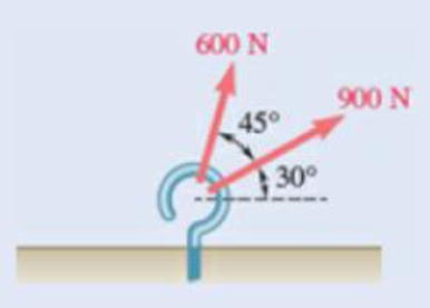
Fig. P2.1
Expert Solution & Answer
Want to see the full answer?
Check out a sample textbook solution
Students have asked these similar questions
(read image)
(read image)
6: Refer to the figure.Given: W1 = 200 kN/m; W2 = 300 kN/m; L1 = 2 m; L2 = 3 m; L3 = 2 m(a) Calculate the total length L so that the resulting upward pressureq is uniform. (b) draw the shear and moment diagram and determinethe maximum shear, maximum positive and negative bendingmoments.
Chapter 2 Solutions
Vector Mechanics for Engineers: Statics
Ch. 2.1 - Two forces are applied as shown to a hook....Ch. 2.1 - Two forces are applied as shown to a bracket...Ch. 2.1 - Two forces P and Q are applied as shown at point A...Ch. 2.1 - Two forces P and Q are applied as shown at point A...Ch. 2.1 - A stake is being pulled out of the ground by means...Ch. 2.1 - A telephone cable is clamped at A to the pole AB....Ch. 2.1 - A telephone cable is clamped at A to the pole AB....Ch. 2.1 - A disabled automobile is pulled by means of two...Ch. 2.1 - A disabled automobile is pulled by means of two...Ch. 2.1 - Two forces are applied as shown to a hook support....
Ch. 2.1 - A steel tank is to be positioned in an excavation....Ch. 2.1 - A steel tank is to be positioned in an excavation....Ch. 2.1 - A steel tank is to be positioned in an excavation....Ch. 2.1 - For the hook support of Prob. 2.10, determine by...Ch. 2.1 - The barge B is pulled by two tugboats A and C. At...Ch. 2.1 - Solve Prob. 2.1 by trigonometry.Ch. 2.1 - Solve Prob. 2.4 by trigonometry.Ch. 2.1 - For the stake of Prob. 2.5, knowing that the...Ch. 2.1 - Two structural members A and B are bolted to a...Ch. 2.1 - Two structural members A and B are bolted to a...Ch. 2.2 - Determine the x and y components of each of the...Ch. 2.2 - Determine the x and y components of each of die...Ch. 2.2 - Determine the x and y components of each of the...Ch. 2.2 - Determine the x and y components of each of the...Ch. 2.2 - Member BC exerts on member AC a force P directed...Ch. 2.2 - Member BD exerts on member ABC a force P directed...Ch. 2.2 - The hydraulic cylinder BC exerts cm member AB a...Ch. 2.2 - Cable AC exerts on beam AD a force P directed...Ch. 2.2 - The hydraulic cylinder BD exerts on member ABC a...Ch. 2.2 - The guy wire BD exerts on the telephone pole AC a...Ch. 2.2 - Determine the resultant of the three forces of...Ch. 2.2 - Determine the resultant of the three forces of...Ch. 2.2 - Determine the resultant of the three forces of...Ch. 2.2 - Determine the resultant of the three forces of...Ch. 2.2 - Knowing that = 35, determine the resultant of the...Ch. 2.2 - Knowing that the tension in cable BC is 725 N,...Ch. 2.2 - Knowing that = 40, determine the resultant of the...Ch. 2.2 - Knowing that = 75, determine the resultant of the...Ch. 2.2 - PROBLEM 2.39 A collar that can slide on a vertical...Ch. 2.2 - Prob. 2.40PCh. 2.2 - PROBLEM 2.41 Determine (a) the required tension in...Ch. 2.2 - PROBLEM 2.42 For the block of Problems 2.37 and...Ch. 2.3 - Two cables are tied together at C and loaded as...Ch. 2.3 - Two forces of magnitude TA = 8 kips and TB = 15...Ch. 2.3 - The 60-lb collar A can slide on a frictionless...Ch. 2.3 - A chairlift has been stopped in the position...Ch. 2.3 - Two cables are tied together at C and are loaded...Ch. 2.3 - Two cables are tied together at C and are loaded...Ch. 2.3 - Two cables are tied together at C and loaded as...Ch. 2.3 - Two cables are tied together at C and are loaded...Ch. 2.3 - Two cables are tied together at C and are loaded...Ch. 2.3 - Knowing that = 20, determine the tension (a) in...Ch. 2.3 - Two cables are tied together at C and are loaded...Ch. 2.3 - Two cables are tied together at C and are loaded...Ch. 2.3 - Two forces P and Q are applied as shown to an...Ch. 2.3 - Prob. 2.52PCh. 2.3 - A welded connection is in equilibrium under the...Ch. 2.3 - A welded connection is in equilibrium under the...Ch. 2.3 - A sailor is being rescued using a boatswains chair...Ch. 2.3 - A sailor is being rescued using a boatswains chair...Ch. 2.3 - For the cables of Prob. 2.44, find the value of ...Ch. 2.3 - For the cables of Prob. 2.46, it is known that the...Ch. 2.3 - For the situation described in Fig. P2.48,...Ch. 2.3 - Two cables tied together at C are loaded as shown....Ch. 2.3 - A movable bin and its contents have a combined...Ch. 2.3 - Free-Body Diagram...Ch. 2.3 - Collar A is connected as shown to a 50-lb load and...Ch. 2.3 - Collar A is connected as shown to a 50-lb load and...Ch. 2.3 - A cable loop of length 1.5 m is placed around a...Ch. 2.3 - A 200-kg crate is to be supported by the...Ch. 2.3 - A 600-lb crate is supported by several...Ch. 2.3 - Solve parts b and d of Prob. 2.67, assuming that...Ch. 2.3 - A load Q is applied to the pulley C, which can...Ch. 2.3 - An 1800-N load Q is applied to pulley C, which can...Ch. 2.4 - Determine (a) the x, y, and z components of the...Ch. 2.4 - Determine (a) the x, y, and z components of the...Ch. 2.4 - A gun is aimed at a point A located 35 east of...Ch. 2.4 - Solve Prob. 2.73 assuming that point A is located...Ch. 2.4 - Prob. 2.75PCh. 2.4 - Prob. 2.76PCh. 2.4 - Cable AB is 65 ft long, and the tension in that...Ch. 2.4 - PROBLEM 2.78 Cable AC is 70 ft long, and the...Ch. 2.4 - Prob. 2.79PCh. 2.4 - Determine the magnitude and direction of the force...Ch. 2.4 - Prob. 2.81PCh. 2.4 - A force acts at the origin of a coordinate system...Ch. 2.4 - A force F of magnitude 210 N acts at the origin of...Ch. 2.4 - Prob. 2.84PCh. 2.4 - Two cables BG and BH are attached to frame ACD as...Ch. 2.4 - Two cables BG and BH are attached to frame ACD as...Ch. 2.4 - In order to move a wrecked truck, two cables are...Ch. 2.4 - In order to move a wrecked truck, two cables are...Ch. 2.4 - A rectangular plate is supported by three cables...Ch. 2.4 - A rectangular plate is supported by three cables...Ch. 2.4 - Find the magnitude and direction of the resultant...Ch. 2.4 - Find the magnitude and direction of the resultant...Ch. 2.4 - Knowing that the tension is 425 lb in cable AB and...Ch. 2.4 - Knowing that the tension is 510 lb in cable AB and...Ch. 2.4 - For the frame of Prob. 2.85, determine the...Ch. 2.4 - For the plate of Prob. 2.89; determine the...Ch. 2.4 - The boom OA carries a load P and is supported by...Ch. 2.4 - Prob. 2.98PCh. 2.5 - Three cables are used to tether a balloon as...Ch. 2.5 - A container of mass m = 120 kg is supported by...Ch. 2.5 - A 150-lb cylinder is supported by two cables AC...Ch. 2.5 - A transmission tower is held by three guy wires...Ch. 2.5 - A container is supported by three cables that are...Ch. 2.5 - A container is supported by three cables that are...Ch. 2.5 - Three cables are used to tether a balloon as...Ch. 2.5 - Three cables are used to tether a balloon as...Ch. 2.5 - A crate is supported by three cables as shown....Ch. 2.5 - A crate is supported by three cables as shown....Ch. 2.5 - A 12-lb circular plate of 7-in. radius is...Ch. 2.5 - Prob. 2.106PCh. 2.5 - Three cables are connected at A, where the forces...Ch. 2.5 - Fig. P2.107 and P2.108 2.108 Three cables are...Ch. 2.5 - A rectangular plate is supported by three cables...Ch. 2.5 - A rectangular plate is supported by three cables...Ch. 2.5 - A transmission tower is held by three guy wires...Ch. 2.5 - A transmission tower is held by three guy wires...Ch. 2.5 - In trying to move across a slippery icy surface, a...Ch. 2.5 - Fig. P2.113 2.114 Solve Prob. 2.113 assuming that...Ch. 2.5 - For the rectangular plate of Probs. 2.109 and...Ch. 2.5 - PROBLEM 2.116 For the cable system of Problems...Ch. 2.5 - PROBLEM 2.117 For the cable system of Problems...Ch. 2.5 - Three cables are connected at D, where an upward...Ch. 2.5 - Prob. 2.119PCh. 2.5 - Three wires are connected at point D, which is...Ch. 2.5 - A container of weight W is suspended from ring A,...Ch. 2.5 - Knowing that the tension in cable AC of the system...Ch. 2.5 - A container of weight W is suspended from ring A....Ch. 2.5 - For the system of Prob. 2.123, determine W and P...Ch. 2.5 - Fig. P2.113 2.114 Solve Prob. 2.113 assuming that...Ch. 2.5 - Prob. 2.126PCh. 2 - Two forces P and Q are applied to the lid of a...Ch. 2 - Determine the x and y components of each of the...Ch. 2 - A hoist trolley is subjected to the three forces...Ch. 2 - Knowing that = 55 and that boom AC exerts on pin...Ch. 2 - Two cables are tied together at C and loaded as...Ch. 2 - Two cables tied together at C are loaded as shown....Ch. 2 - The end of the coaxial cable AE is attached to the...Ch. 2 - Knowing that the tension in cable AC is 2130 N,...Ch. 2 - Find the magnitude and direction of the resultant...Ch. 2 - Cable BAC passes through a frictionless ring A and...Ch. 2 - Collars A and B are connected by a 25-in.-lang...Ch. 2 - Fig. P2.137 and P2.138 2.138 Collars A and B are...
Additional Engineering Textbook Solutions
Find more solutions based on key concepts
A nozzle at A discharges water with an initial velocity of 36 ft/s at an angle with the horizontal. Determine ...
Vector Mechanics For Engineers
The solid steel shaft AC has a diameter of 25 mm and is supported by smooth bearings at D and E. It is coupled ...
Mechanics of Materials (10th Edition)
Why is the study of database technology important?
Database Concepts (8th Edition)
Assume a telephone signal travels through a cable at two-thirds the speed of light. How long does it take the s...
Electric Circuits. (11th Edition)
What are the design issues for character string types?
Concepts Of Programming Languages
17–1C A high-speed aircraft is cruising in still air. How does the temperature of air at the nose of the aircra...
Thermodynamics: An Engineering Approach
Knowledge Booster


Learn more about
Need a deep-dive on the concept behind this application? Look no further. Learn more about this topic, mechanical-engineering and related others by exploring similar questions and additional content below.Similar questions
- A six cylinder, four-stroke diesel engine develops a power of 200 kW at 2000 rpm. The bsfc is 0.2 kW/kg h of fuel with 34.9° API. The fuel is injected at an average pressure of 350 bar and the pressure in the combustion chamber is 40 bar. Assuming Ca for injector 0.75 and the atmospheric pressure 1 bar. Determine the period of injection in seconds if the total orifice area required per injector is 0.4876 × 10⁻⁶ m².arrow_forwardTrieed a detailed drawing Win explanatio LL Antsmi 1981x pu + 96252 اه 6. The Pre-combustion chamber design engines employ nozzle type commonly referred to as a ....... a. inward-opening nozzle b. multiple-hole nozzle. c. pintle nozzle. d. none of these. 7. If the temperature of the spark plug tip is less than 350 °C, ......... a. the plug might not work. b. the carbon deposits would increase. 8. Port injection sprays fuel....... c. pre-ignition will occur. d. none of these. a. towards the intake valve. b. in the engine cylinder. c. in the throttle body assembly. d. none of these. 9. When the fuel-air mixture changed from best power to a richer ratio, the spark advance should be........ a. increased. b. decreased. c. left unchanged. d. none of these. d. none of these. 10. Spark plugs are classified as hot plugs and cold plugs depending upon ........ a. spark gap. b. the type of plug c. the operating temperature insulator. range of the electrode tip. ---20125 750 x2.01 SP 5.arrow_forwardA 1. How does the octane number (O.N.) of the fuel a. Higher ignition advance is required for a high O.N. fuel. b. Higher ignition retard is required for a high O.N. fuel. affect spark ing:d. Nou does not affect spark timing. c. The octane number 2. How does the ignition system account for load change? these. of a. The throttle b. The vacuum ignition governor c. The mechanism of d. None of is wide opened. provide additional spark advance at part throttle positions. centrifugal advance does the job. these. 3. In the common rail fuel system the fuel is metered by ........ a. low pressure pump. b. injectors. c. high pressure pump. d. none of these. 4.......... is the time period, measured in degrees of cam rotation, during which the contact points remain closed between each opening. a. Distributor. b. Dwell. c. ECU. d. none of these. 5. The trigger wheel in TCI system replaces the ......... used in a contact breaker distributor. a. pickup coil. b. distributor cam. c. condenser. 750 x2.01…arrow_forward
- a い يكا 4 +91- pu Answer the following statements by true or false, giving the reason for your answer: 1. Injection pressure in CI engines should be sufficiently high. 2. The purpose of the condenser in battery ignition system is to prevent spark in the ignition coil assembly. 3. An idling engine requires lean mixture of fuel and air. 4. Factors which decide optimum engine firing order are engine vibration, engine cooling and back pressure. 5. It is the duty of the header to control over speeding during CI engine operation when drastic reduction in load occurs. ---20125 750 x2.01 SParrow_forward6. The Pre-combustion chamber design engines employ nozzle type commonly referred to as a a. inward-opening nozzle b. multiple-hole nozzle. c. pintle nozzle. d. none of these. 7. If the temperature of the spark plug tip is less than 350 °C, ........ a. the plug might b. the carbon deposits not work. would increase. c. pre-ignition will occur. d. none of these. 8. Port injection sprays fuel........ a. towards the intake valve. b. in the engine cylinder. c. in the throttle body d. none of assembly. these. 9. When the fuel-air mixture changed from best power to a richer ratio, the spark advance should be ........ a. increased. b. decreased. c. left unchanged. d. none of these. 10. Spark plugs are classified as hot plugs and cold plugs depending upon a. spark gap. b. the type of plug c. the operating temperature d. none of these. range of the electrode tip. insulator.arrow_forward1: A H = 6 m cantilever retaining wall is subjected to a soil pressurelinearly varying from zero at the top to 90 kPa at the bottom. As an additionalsupport, it is anchored at depth y = 2 m. with maximum tension equal to 25kN. Assume that the stem provides fully retrained support. Draw the shearand moment diagram of the wall to calculate the following: (a) Maximumpositive bending moment per linear meter; (b) maximum negative bendingmoment per linear meter; (c) maximum shear force per linear meter.arrow_forward
- CORRECT AND DETAILED SOLUTION WITH COMPLETE FBD ONLY. I WILL UPVOTE. 9: The beam shown has a width of 80 mm and its allowable bending stress is not to exceed 120 MPa. Calculatethe required depth of the beam.arrow_forwardPROBLEM 4: A pre-stressed concrete pile of length L (m) is to be picked up by crane cables at two points, both equidistant from the ends. If the concrete pile has a cross-sectional area of A (m²) and concrete has unit weight of Yc (kN/m³), calculate the distance of the pick-up points from the end in terms of pile length. (Hint: to minimize the absolute maximum moment, the maximum negative and maximum negative moments should be equal)arrow_forwardCorrect and detailed solution only. Complete fbd. I will upvote.arrow_forward
- 3: Given the shear diagram of the simply supported beam shown, properly illustrate the load and bendingmoment diagram considering that the beam carries a 5 kN-m clockwise moment at C.arrow_forwardCORRECT AND DETAILED SOLUTION WITH COMPLETE FBD ONLY. I WILL UPVOTE. 8: A 2-m cantilever beam with cross-sectionshown carries a uniformly distributed load of 12 kN/m. Dueto fixture requirements, a hole of diameter 150 mm isremoved from the cross-section. (a) Calculate themaximum normal compressive stress. (b) Calculate themaximum normal tensile stress. (c) Calculate anddetermine the state of stress at the lowest point of thecircular hole.arrow_forward5: A 12-m simply supported bridge is constructed with 100-mm concrete slab deck supported by precastconcrete stringers spaced 800 mm on center. Analyze the stringers when subjected to a moving load consisting of 3 evenly spaced axle loads at 3 m and equivalent to 20 kN, 30 kN and 40 kN respectively. The self-weight of the stringers is 8.5 kN/m and the concrete deck has a unit weight of 24 kN/m3 . Neglect all other superimposed loads. Calculate: (a) the maximum shear force in the stringers; (b) the maximum bending moment in the stringers.arrow_forward
arrow_back_ios
SEE MORE QUESTIONS
arrow_forward_ios
Recommended textbooks for you
 Elements Of ElectromagneticsMechanical EngineeringISBN:9780190698614Author:Sadiku, Matthew N. O.Publisher:Oxford University Press
 Mechanics of Materials (10th Edition)Mechanical EngineeringISBN:9780134319650Author:Russell C. HibbelerPublisher:PEARSON
 Thermodynamics: An Engineering ApproachMechanical EngineeringISBN:9781259822674Author:Yunus A. Cengel Dr., Michael A. BolesPublisher:McGraw-Hill Education
 Control Systems EngineeringMechanical EngineeringISBN:9781118170519Author:Norman S. NisePublisher:WILEY
 Mechanics of Materials (MindTap Course List)Mechanical EngineeringISBN:9781337093347Author:Barry J. Goodno, James M. GerePublisher:Cengage Learning
 Engineering Mechanics: StaticsMechanical EngineeringISBN:9781118807330Author:James L. Meriam, L. G. Kraige, J. N. BoltonPublisher:WILEY
Elements Of Electromagnetics
Mechanical Engineering
ISBN:9780190698614
Author:Sadiku, Matthew N. O.
Publisher:Oxford University Press
Mechanics of Materials (10th Edition)
Mechanical Engineering
ISBN:9780134319650
Author:Russell C. Hibbeler
Publisher:PEARSON
Thermodynamics: An Engineering Approach
Mechanical Engineering
ISBN:9781259822674
Author:Yunus A. Cengel Dr., Michael A. Boles
Publisher:McGraw-Hill Education
Control Systems Engineering
Mechanical Engineering
ISBN:9781118170519
Author:Norman S. Nise
Publisher:WILEY
Mechanics of Materials (MindTap Course List)
Mechanical Engineering
ISBN:9781337093347
Author:Barry J. Goodno, James M. Gere
Publisher:Cengage Learning
Engineering Mechanics: Statics
Mechanical Engineering
ISBN:9781118807330
Author:James L. Meriam, L. G. Kraige, J. N. Bolton
Publisher:WILEY
How to balance a see saw using moments example problem; Author: Engineer4Free;https://www.youtube.com/watch?v=d7tX37j-iHU;License: Standard Youtube License