
Fox And Mcdonald's Introduction To Fluid Mechanics
9th Edition
ISBN: 9781118921876
Author: Pritchard, Philip J.; Leylegian, John C.; Bhaskaran, Rajesh
Publisher: WILEY
expand_more
expand_more
format_list_bulleted
Videos
Textbook Question
Chapter 2, Problem 40P
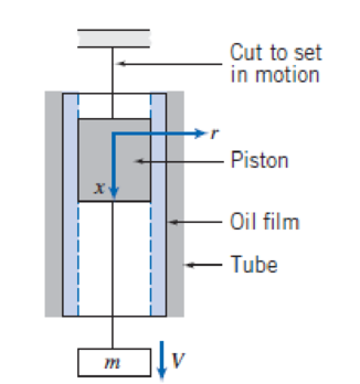
A 73-mm-diameter aluminum (SG = 2.64) piston of 100-mm length resides in a stationary 75-mm-inner-diameter steel tube lined with SAE 10W-30 oil at 25°C. A mass m = 2 kg is suspended from the free end of the piston. The piston is set into motion by cutting a support cord. What is the terminal velocity of mass m? Assume a linear velocity profile within the oil.
Expert Solution & Answer
Want to see the full answer?
Check out a sample textbook solution
Students have asked these similar questions
An ordinary egg can be approximated as a 5.5-cm-diameter sphere. The egg is initially at a uniform temperature of 8°C and is dropped into boiling water at 97°C. Taking the properties of the egg to be ρ = 1020 kg/m3 and cp = 3.32 kJ/kg·°C, determine how much heat is transferred to the egg by the time the average temperature of the egg rises to 82°C.
The heat transferred to the egg in this case is kJ.
Ship construction question. Sketch and describe the forward arrangements of a ship. Include componets of the structure and a explanation of each part/ term.
I don't want an AI solution please.
Chapter 2 Solutions
Fox And Mcdonald's Introduction To Fluid Mechanics
Ch. 2 - For the velocity fields given below, determine:...Ch. 2 - For the velocity fields given below, determine:...Ch. 2 - A viscous liquid is sheared between two parallel...Ch. 2 - For the velocity field V=Ax2yi+Bxy2j, where A = 2...Ch. 2 - A fluid flow has the following velocity...Ch. 2 - When an incompressible, nonviscous fluid flows...Ch. 2 - For the free vortex flow the velocities are t =...Ch. 2 - For the forced vortex flow the velocities are t =...Ch. 2 - A velocity field is specified as V=axyi+by2j,...Ch. 2 - A velocity field is given by V=ax3i+bxy3j, where a...
Ch. 2 - The velocity for a steady, incompressible flow in...Ch. 2 - The flow field for an atmospheric flow is given by...Ch. 2 - For the velocity field V=AxiAyj,, where A = 2s 1....Ch. 2 - A velocity field in polar coordinates is given...Ch. 2 - The flow of air near the Earths surface is...Ch. 2 - A velocity field is given by V=aytibxj, where a =...Ch. 2 - Air flows downward toward an infinitely wide...Ch. 2 - Consider the flow described by the velocity field...Ch. 2 - Consider the velocity field V = axi + by(1 + ct)...Ch. 2 - Consider the flow field given in Eulerian...Ch. 2 - A velocity field is given by V=axti+byj, where A =...Ch. 2 - Consider the garden hose of Fig. 2.5. Suppose the...Ch. 2 - Consider the velocity field of Problem 2.18. Plot...Ch. 2 - Streaklines are traced out by neutrally buoyant...Ch. 2 - Consider the flow field V=axti+bj, where a = 1/s2...Ch. 2 - A flow is described by velocity field V=ay2i+bj,...Ch. 2 - Tiny hydrogen bubbles are being used as tracers to...Ch. 2 - A flow is described by velocity field V=ai+bxj,...Ch. 2 - A flow is described by velocity field V=ayi+btj,...Ch. 2 - A flow is described by velocity field V=ati+bj,...Ch. 2 - The variation with temperature of the viscosity of...Ch. 2 - The variation with temperature of the viscosity of...Ch. 2 - Some experimental data for the viscosity of helium...Ch. 2 - The velocity distribution for laminar flow between...Ch. 2 - What is the ratio between the viscosities of air...Ch. 2 - Calculate velocity gradients and shear stress for...Ch. 2 - A very large thin plate is centered in a gap of...Ch. 2 - A female freestyle ice skater, weighing 100 lbf,...Ch. 2 - A block of mass 10 kg and measuring 250 mm on each...Ch. 2 - A 73-mm-diameter aluminum (SG = 2.64) piston of...Ch. 2 - A vertical gap 25 mm wide of infinite extent...Ch. 2 - A cylinder 8 in. in diameter and 3 ft long is...Ch. 2 - Crude oil at 20C fills the space between two...Ch. 2 - The piston in Problem 2.40 is traveling at...Ch. 2 - A block of mass M slides on a thin film of oil....Ch. 2 - A block 0.1 m square, with 5 kg mass, slides down...Ch. 2 - A torque of 4 N m is required to rotate the...Ch. 2 - A circular disk of diameter d is slowly rotated in...Ch. 2 - The fluid drive shown transmits a torque T for...Ch. 2 - A block that is a mm square slides across a flat...Ch. 2 - In a food-processing plant, honey is pumped...Ch. 2 - SAE 10W-30 oil at 100C is pumped through a tube L...Ch. 2 - The lubricant has a kinematic viscosity of 2:8105...Ch. 2 - Calculate the approximate viscosity of the oil....Ch. 2 - Calculate the approximate power lost in friction...Ch. 2 - Fluids of viscosities 1 = 0.1 Ns/m2 and 2 = 0.15...Ch. 2 - A concentric cylinder viscometer may be formed by...Ch. 2 - A concentric cylinder viscometer is driven by a...Ch. 2 - A shaft with outside diameter of 18 mm turns at 20...Ch. 2 - A shock-free coupling for a low-power mechanical...Ch. 2 - A proposal has been made to use a pair of parallel...Ch. 2 - The cone and plate viscometer shown is an...Ch. 2 - A viscometer is used to measure the viscosity of a...Ch. 2 - A concentric-cylinder viscometer is shown. Viscous...Ch. 2 - Design a concentric-cylinder viscometer to measure...Ch. 2 - A cross section of a rotating bearing is shown....Ch. 2 - Small gas bubbles form in soda when a bottle or...Ch. 2 - You intend to gently place several steel needles...Ch. 2 - According to Folsom [6], the capillary rise h...Ch. 2 - Calculate and plot the maximum capillary rise of...Ch. 2 - Calculate the maximum capillary rise of water...Ch. 2 - Calculate the maximum capillary depression of...Ch. 2 - Water usually is assumed to be incompressible when...Ch. 2 - The viscous boundary layer velocity profile shown...Ch. 2 - In a food industry process, carbon tetrachloride...Ch. 2 - What is the Reynolds number of water at 20C...Ch. 2 - A supersonic aircraft travels at 2700 km/hr at an...Ch. 2 - SAE 30 oil at 100C flows through a 12-mm-diameter...Ch. 2 - A seaplane is flying at 100 mph through air at...Ch. 2 - An airliner is cruising at an altitude of 5.5 km...
Additional Engineering Textbook Solutions
Find more solutions based on key concepts
Code an SQL statement that creates a table with all columns from the parent and child tables in your answer to ...
Database Concepts (8th Edition)
Assume mystrinc references a string. Write a statement that uses a slicing expression and displays the first 3 ...
Starting Out with Python (4th Edition)
In Exercises 41 through 46, identify the errors. Dim9WAsDouble9W=2*9WIstoutput.Items.Add(9W)
Introduction To Programming Using Visual Basic (11th Edition)
A loading causes the member to deform into the dashed shape. Explain how to determine the normal strains CD and...
Mechanics of Materials (10th Edition)
If the block is held in the equilibrium position shown, determine the mass of the block at D.
INTERNATIONAL EDITION---Engineering Mechanics: Statics, 14th edition (SI unit)
Comprehension check 12-11
The decay of a radioactive isotope was tracked over a number of hours, resulting in t...
Thinking Like an Engineer: An Active Learning Approach (4th Edition)
Knowledge Booster


Learn more about
Need a deep-dive on the concept behind this application? Look no further. Learn more about this topic, mechanical-engineering and related others by exploring similar questions and additional content below.Similar questions
- 42 PART 1 Introduction A. E. I constant FIGURE 1.22 A fixed-pinned beam. 1.6 Find the stress distribution in the beam shown in Fig. 1.22 using two beam elements.arrow_forward1.4 Using a one-beam element idealization, find the stress distribution under a load of P for the uniform cantilever beam shown in Fig. 1.20. A, E, I constant L FIGURE 1.20 A uniform cantilever beamarrow_forwardMechanical engineering,FBD required.arrow_forward
- Solve this problem and show all of the workarrow_forwardPlease Please use MATLAB with codes and graph. Recreate the following four Figures of the textbook using MATLAB and the appropriate parameters. Comment on your observations for each Figure. List all of the parameters that you have used. The figure is attached below.arrow_forwardPlease only step 6 (last time I asked it was cut off at that point)arrow_forward
- Please Please use a MATLAB with codes and grap. Recreate the following four Figures of the textbook using MATLAB and the appropriate parameters. Comment on your observations for each Figure. List all of the parameters that you have used. The figure attached below.arrow_forwardI REPEAT!!!!! I NEED HANDDRAWING!!!!! NOT A USELESS EXPLANATION!!!! I REPEAT SUBMIT A HANDDRAWING IF YOU CANNOT UNDERSTAND THIS SKIP IT ! I need the real handdrawing complete it by adding these : Pneumatic Valves Each linear actuator must be controlled by a directional control valve (DCV) (e.g., 5/2 or 4/2 valve). The bi-directional motor requires a reversible valve to change rotation direction. Pressure Regulators & Air Supply Include two pressure regulators as per the assignment requirement. Show the main compressed air supply line connecting all components. Limit Switches & Safety Features Attach limit switches to each actuator to detect positions. Implement a two-handed push-button safety system to control actuator movement. Connections Between Components Draw air supply lines linking the compressor, valves, and actuators. Clearly label all inputs and outputs for better understanding.arrow_forwardI need the real handdrawing complete it by adding these : Pneumatic Valves Each linear actuator must be controlled by a directional control valve (DCV) (e.g., 5/2 or 4/2 valve). The bi-directional motor requires a reversible valve to change rotation direction. Pressure Regulators & Air Supply Include two pressure regulators as per the assignment requirement. Show the main compressed air supply line connecting all components. Limit Switches & Safety Features Attach limit switches to each actuator to detect positions. Implement a two-handed push-button safety system to control actuator movement. Connections Between Components Draw air supply lines linking the compressor, valves, and actuators. Clearly label all inputs and outputs for better understanding.arrow_forward
arrow_back_ios
SEE MORE QUESTIONS
arrow_forward_ios
Recommended textbooks for you
 Elements Of ElectromagneticsMechanical EngineeringISBN:9780190698614Author:Sadiku, Matthew N. O.Publisher:Oxford University Press
 Mechanics of Materials (10th Edition)Mechanical EngineeringISBN:9780134319650Author:Russell C. HibbelerPublisher:PEARSON
 Thermodynamics: An Engineering ApproachMechanical EngineeringISBN:9781259822674Author:Yunus A. Cengel Dr., Michael A. BolesPublisher:McGraw-Hill Education
 Control Systems EngineeringMechanical EngineeringISBN:9781118170519Author:Norman S. NisePublisher:WILEY
 Mechanics of Materials (MindTap Course List)Mechanical EngineeringISBN:9781337093347Author:Barry J. Goodno, James M. GerePublisher:Cengage Learning
 Engineering Mechanics: StaticsMechanical EngineeringISBN:9781118807330Author:James L. Meriam, L. G. Kraige, J. N. BoltonPublisher:WILEY
Elements Of Electromagnetics
Mechanical Engineering
ISBN:9780190698614
Author:Sadiku, Matthew N. O.
Publisher:Oxford University Press
Mechanics of Materials (10th Edition)
Mechanical Engineering
ISBN:9780134319650
Author:Russell C. Hibbeler
Publisher:PEARSON
Thermodynamics: An Engineering Approach
Mechanical Engineering
ISBN:9781259822674
Author:Yunus A. Cengel Dr., Michael A. Boles
Publisher:McGraw-Hill Education
Control Systems Engineering
Mechanical Engineering
ISBN:9781118170519
Author:Norman S. Nise
Publisher:WILEY
Mechanics of Materials (MindTap Course List)
Mechanical Engineering
ISBN:9781337093347
Author:Barry J. Goodno, James M. Gere
Publisher:Cengage Learning
Engineering Mechanics: Statics
Mechanical Engineering
ISBN:9781118807330
Author:James L. Meriam, L. G. Kraige, J. N. Bolton
Publisher:WILEY
Physics 33 - Fluid Statics (1 of 10) Pressure in a Fluid; Author: Michel van Biezen;https://www.youtube.com/watch?v=mzjlAla3H1Q;License: Standard YouTube License, CC-BY