EP ENGR.MECH.-MOD.MASTERING ACCESS
15th Edition
ISBN: 9780134867267
Author: HIBBELER
Publisher: PEARSON CO
expand_more
expand_more
format_list_bulleted
Videos
Textbook Question
Chapter 2, Problem 3FP
Determine the magnitude of the resultant force and its direction measured counterclockwise from the positive x axis.
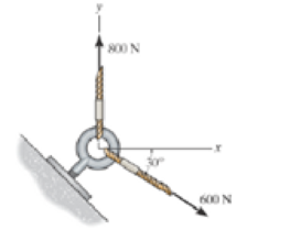
Prob. F2-3
Expert Solution & Answer

Learn your wayIncludes step-by-step video

schedule06:44
Students have asked these similar questions
Please Please use a MATLAB with codes and grap. Recreate the following four Figures of the textbook using MATLAB and the appropriate parameters. Comment on your observations for each Figure. List all of the parameters that you have used. The figure attached below.
I REPEAT!!!!! I NEED HANDDRAWING!!!!! NOT A USELESS EXPLANATION!!!! I REPEAT SUBMIT A HANDDRAWING IF YOU CANNOT UNDERSTAND THIS SKIP IT !
I need the real handdrawing complete it by adding these :
Pneumatic Valves
Each linear actuator must be controlled by a directional control valve (DCV) (e.g., 5/2 or 4/2 valve).
The bi-directional motor requires a reversible valve to change rotation direction.
Pressure Regulators & Air Supply
Include two pressure regulators as per the assignment requirement.
Show the main compressed air supply line connecting all components.
Limit Switches & Safety Features
Attach limit switches to each actuator to detect positions.
Implement a two-handed push-button safety system to control actuator movement.
Connections Between Components
Draw air supply lines linking the compressor, valves, and actuators.
Clearly label all inputs and outputs for better understanding.
Chapter 2 Solutions
EP ENGR.MECH.-MOD.MASTERING ACCESS
Ch. 2 - Determine the magnitude of the resultant force...Ch. 2 - Two forces act on the hook. Determine the...Ch. 2 - Determine the magnitude of the resultant force and...Ch. 2 - Resolve the 30-lb force into components along the...Ch. 2 - The force F = 450 lb acts on the frame. Resolve...Ch. 2 - If force F is to have a component along the u axis...Ch. 2 - Determine the magnitude of the resultant force FR...Ch. 2 - Resolve the force F1 into components acting along...Ch. 2 - Resolve the force F2 into components acting along...Ch. 2 - Prob. 10P
Ch. 2 - Determine the angle for connecting member A to...Ch. 2 - Determine the magnitude and direction of the...Ch. 2 - Determine the magnitude and direction of the...Ch. 2 - Determine the magnitude and direction of FA SO...Ch. 2 - If the resultant force of the two tugboats is 3...Ch. 2 - If FB = 3 kN and = 45, determine the magnitude of...Ch. 2 - If the resultant force of the two tugboats is...Ch. 2 - Resolve each force acting on the post into its x...Ch. 2 - Determine the magnitude and direction of the...Ch. 2 - Prob. 9FPCh. 2 - If the resultant force acting on the bracket is to...Ch. 2 - If the magnitude of the resultant force acting on...Ch. 2 - Determine the magnitude of the resultant force and...Ch. 2 - Resolve each force acting on the gusset plate into...Ch. 2 - Determine the magnitude of the resultant force...Ch. 2 - Prob. 39PCh. 2 - Determine the magnitude of the resultant force and...Ch. 2 - Determine the magnitude of the resultant force and...Ch. 2 - Express F1, F2, and F3 as Cartesian vectors.Ch. 2 - Prob. 43PCh. 2 - Determine the magnitude and orientation of FB so...Ch. 2 - Prob. 48PCh. 2 - Express F1, F2, and F3 as Cartesian vectors.Ch. 2 - Prob. 56PCh. 2 - If the resultant force acting on the bracket is...Ch. 2 - Prob. 58PCh. 2 - If F = 5 kN and = 30, determine the magnitude of...Ch. 2 - Determine the coordinate direction angles of the...Ch. 2 - Prob. 14FPCh. 2 - Prob. 15FPCh. 2 - Prob. 16FPCh. 2 - Prob. 17FPCh. 2 - Prob. 18FPCh. 2 - Prob. 61PCh. 2 - Prob. 66PCh. 2 - Determine the magnitude and coordinate direction...Ch. 2 - Specify the magnitude and coordinate direction...Ch. 2 - Prob. 73PCh. 2 - Prob. 74PCh. 2 - Prob. 75PCh. 2 - Prob. 77PCh. 2 - Prob. 79PCh. 2 - Prob. 81PCh. 2 - Prob. 82PCh. 2 - If the direction of the resultant force acting on...Ch. 2 - Express the position vector rAB in Cartesian...Ch. 2 - Prob. 20FPCh. 2 - Express the force as a Cartesian vector. Prob....Ch. 2 - Prob. 22FPCh. 2 - Prob. 23FPCh. 2 - Prob. 24FPCh. 2 - Determine the length of the connecting rod AB by...Ch. 2 - Prob. 88PCh. 2 - Prob. 90PCh. 2 - Prob. 91PCh. 2 - Determine the magnitude and coordinate direction...Ch. 2 - Prob. 98PCh. 2 - Prob. 25FPCh. 2 - Determine the angle between the force and the...Ch. 2 - Prob. 27FPCh. 2 - Prob. 28FPCh. 2 - Find the magnitude of the projected component of...Ch. 2 - Prob. 30FPCh. 2 - Determine the magnitudes of the components of the...Ch. 2 - Determine the components of F that act along rodAC...Ch. 2 - Determine the magnitudes of the components of F =...Ch. 2 - Prob. 111PCh. 2 - Prob. 112PCh. 2 - Determine the angle between the two cables...Ch. 2 - Determine the angle between the cables AB and AC....Ch. 2 - Determine the magnitude of the projected component...Ch. 2 - Determine the magnitude of the projected component...Ch. 2 - Determine the magnitudes of the projection of the...Ch. 2 - Determine the magnitude of the resultant force FR...Ch. 2 - Prob. 5RPCh. 2 - Prob. 6RPCh. 2 - Prob. 7RPCh. 2 - Prob. 8RP
Additional Engineering Textbook Solutions
Find more solutions based on key concepts
What is an infinite loop? Write the code for an infinite loop.
Starting Out with Java: From Control Structures through Objects (7th Edition) (What's New in Computer Science)
The while loop is a pretest loop.
Starting Out with Python (4th Edition)
Look at the following code: struct PartData { string partName; int idNumber; }; PartData inventory[100]; Write ...
Starting Out with C++ from Control Structures to Objects (9th Edition)
In the circuit shown in Fig. P 7.26, both switches operate together; that is, they either open or close at the ...
Electric Circuits. (11th Edition)
What is the difference between a friend function for a class and a member function for the class?
Problem Solving with C++ (10th Edition)
Why were computer programming languages invented?
Starting Out With Visual Basic (8th Edition)
Knowledge Booster


Learn more about
Need a deep-dive on the concept behind this application? Look no further. Learn more about this topic, mechanical-engineering and related others by exploring similar questions and additional content below.Similar questions
- An elastic bar of the length L and cross section area A is rigidly attached to the ceiling of a room, and it supports a mass M. Due to the acceleration of gravity g the rod deforms vertically. The deformation of the rod is measured by the vertical displacement u(x) governed by the following equations: dx (σ(x)) + b(x) = 0 PDE σ(x) = Edx du Hooke's law (1) b(x) = gp= body force per unit volume where E is the constant Young's modulus, p is the density, and σ(x) the axial stress in the rod. g * I u(x) L 2arrow_forwardAn elastic bar of the length L and cross section area A is rigidly attached to the ceiling of a room, and it supports a mass M. Due to the acceleration of gravity g the rod deforms vertically. The deformation of the rod is measured by the vertical displacement u(x) governed by the following equations: dx (σ(x)) + b(x) = 0 PDE σ(x) = Edx du Hooke's law (1) b(x) = gp= body force per unit volume where E is the constant Young's modulus, p is the density, and σ(x) the axial stress in the rod. g * I u(x) L 2arrow_forwardمتوسعة الفرج بو عمامة المستوى رم الواجب المنزلي رقم 04 تمرین الوان حسب يتمعن العبارات الأتية : A= (+2)+(-45) B=(+13)- C = (+17)-(+13)-(-20)+(-19 D= [(-15)-(+15)]-[(+20) + هست قیم مدرج مبدؤه النقطة ة الطول :tcm A(-2,5): B(+ 2,5) ≤ C (+5) المسافتين : BAD ين الثاني لمستوي مبدؤه 8 وحدتهarrow_forward
- Please do not rely too much on AI, because its answer may be wrong. Please consider it carefully and give your own answer!!!!! You can borrow ideas from AI, but please do not believe its answer.Very very grateful! ( If you write by hand or don't use AI, I'll give you a big thumbs up ) Please do not copy other's work,i will be very very grateful!!Please do not copy other's work,i will be very very grateful!!arrow_forwardA thin uniform rod of mass m and length 2r rests in a smooth hemispherical bowl of radius r. A moment M = mgr horizontal plane. is applied to the rod. Assume that the bowl is fixed and its rim is in the HINT: It will help you to find the length l of that portion of the rod that remains outside the bowl. M 2r Ꮎ a) How many degrees of freedom does this system have? b) Write an equation for the virtual work in terms of the angle 0 and the motion of the center of mass (TF) c) Derive an equation for the variation in the position of the center of mass (i.e., Sŕƒ) a. HINT: Use the center of the bowl as the coordinate system origin for the problem. d) In the case of no applied moment (i.e., M = 0), derive an equation that can be used to solve for the equilibrium angle of the rod. DO NOT solve the equation e) In the case of an applied moment (i.e., M: = mgr 4 -) derive an equation that can be used to solve for the equilibrium angle of the rod. DO NOT solve the equation. f) Can the angle 0 and…arrow_forwardSolve this problem and show all of the workarrow_forward
- Solve this problem and show all of the workarrow_forwardSolve this problem and show all of the workarrow_forwardPlease do not rely too much on chatgpt, because its answer may be wrong. Please consider it carefully and give your own answer. You can borrow ideas from gpt, but please do not believe its answer.Very very grateful! Please do not copy other's work,i will be very very grateful!!Please do not copy other's work,i will be very very grateful!!arrow_forward
- = The frame shown is fitted with three 50 cm diameter frictionless pulleys. A force of F = 630 N is applied to the rope at an angle ◊ 43°. Member ABCD is attached to the wall by a fixed support at A. Find the forces indicated below. Note: The rope is tangent to the pully (D) and not secured at the 3 o'clock position. a b •C *су G E e d BY NC SA 2013 Michael Swanbom Values for dimensions on the figure are given in the following table. Note the figure may not be to scale. Variable Value a 81 cm b 50 cm с 59 cm d 155 cm For all answers, take x as positive to the right and positive upward. At point A, the fixed support exerts a force of: A = + ĴN and a reaction couple of: →> ΜΑ Member CG is in Select an answer magnitude У as k N-m. and carries a force of N.arrow_forwardThe lower jaw AB [Purple 1] and the upper jaw-handle AD [Yellow 2] exert vertical clamping forces on the object at R. The hand squeezes the upper jaw-handle AD [2] and the lower handle BC [Orane 4] with forces F. (Member CD [Red 3] acts as if it is pinned at D, but, in a real vise-grips, its position is actually adjustable.) The clamping force, R, depends on the geometry and on the squeezing force F applied to the handles. Determine the proportionality between the clamping force, R, and the squeezing force F for the dimensions given. d3 d4 R 1 B d1 2 d2 D... d5 F 4 F Values for dimensions on the figure are given in the following table. Note the figure may not be to scale. Variable Value d1 65 mm d2 156 mm d3 50 mm 45 d4 d5 113 mm 30 mm R = Farrow_forwardA triangular distributed load of max intensity w =460 N/m acts on beam AB. The beam is supported by a pin at A and member CD, which is connected by pins at C and D respectively. Determine the reaction forces at A and C. Enter your answers in Cartesian components. Assume the masses of both beam AB and member CD are negligible. cc 040 BY NC SA 2016 Eric Davishahl W A C D -a- B Ул -b- x Values for dimensions on the figure are given in the following table. Note the figure may not be to scale. Variable Value α 5.4 m b 8.64 m C 3.24 m The reaction at A is A = i+ ĴN. λ = i+ Ĵ N. The reaction at C is C =arrow_forward
arrow_back_ios
SEE MORE QUESTIONS
arrow_forward_ios
Recommended textbooks for you
 Elements Of ElectromagneticsMechanical EngineeringISBN:9780190698614Author:Sadiku, Matthew N. O.Publisher:Oxford University Press
 Mechanics of Materials (10th Edition)Mechanical EngineeringISBN:9780134319650Author:Russell C. HibbelerPublisher:PEARSON
 Thermodynamics: An Engineering ApproachMechanical EngineeringISBN:9781259822674Author:Yunus A. Cengel Dr., Michael A. BolesPublisher:McGraw-Hill Education
 Control Systems EngineeringMechanical EngineeringISBN:9781118170519Author:Norman S. NisePublisher:WILEY
 Mechanics of Materials (MindTap Course List)Mechanical EngineeringISBN:9781337093347Author:Barry J. Goodno, James M. GerePublisher:Cengage Learning
 Engineering Mechanics: StaticsMechanical EngineeringISBN:9781118807330Author:James L. Meriam, L. G. Kraige, J. N. BoltonPublisher:WILEY
Elements Of Electromagnetics
Mechanical Engineering
ISBN:9780190698614
Author:Sadiku, Matthew N. O.
Publisher:Oxford University Press
Mechanics of Materials (10th Edition)
Mechanical Engineering
ISBN:9780134319650
Author:Russell C. Hibbeler
Publisher:PEARSON
Thermodynamics: An Engineering Approach
Mechanical Engineering
ISBN:9781259822674
Author:Yunus A. Cengel Dr., Michael A. Boles
Publisher:McGraw-Hill Education
Control Systems Engineering
Mechanical Engineering
ISBN:9781118170519
Author:Norman S. Nise
Publisher:WILEY
Mechanics of Materials (MindTap Course List)
Mechanical Engineering
ISBN:9781337093347
Author:Barry J. Goodno, James M. Gere
Publisher:Cengage Learning
Engineering Mechanics: Statics
Mechanical Engineering
ISBN:9781118807330
Author:James L. Meriam, L. G. Kraige, J. N. Bolton
Publisher:WILEY
How to balance a see saw using moments example problem; Author: Engineer4Free;https://www.youtube.com/watch?v=d7tX37j-iHU;License: Standard Youtube License