
EBK ENGINEERING MECHANICS
15th Edition
ISBN: 9780137616909
Author: HIBBELER
Publisher: VST
expand_more
expand_more
format_list_bulleted
Videos
Textbook Question
Chapter 2, Problem 2FP
Two forces act on the hook. Determine the magnitude of the resultant force.
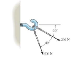
Prob. F2-2
Expert Solution & Answer
Want to see the full answer?
Check out a sample textbook solution
Students have asked these similar questions
I don't want an AI solution please.
I don't want an AI solution please.
1.7 Find the stress distribution in the beam shown in Fig. 1.23 using two beam elements.
A. E. I constant
M₂
T
+
FIGURE 1.23 A fixed-pinned beam subjected to a moment
Chapter 2 Solutions
EBK ENGINEERING MECHANICS
Ch. 2 - Determine the magnitude of the resultant force...Ch. 2 - Two forces act on the hook. Determine the...Ch. 2 - Determine the magnitude of the resultant force and...Ch. 2 - Resolve the 30-lb force into components along the...Ch. 2 - The force F = 450 lb acts on the frame. Resolve...Ch. 2 - If force F is to have a component along the u axis...Ch. 2 - Determine the magnitude of the resultant force FR...Ch. 2 - Resolve the force F1 into components acting along...Ch. 2 - Resolve the force F2 into components acting along...Ch. 2 - Prob. 10P
Ch. 2 - Determine the angle for connecting member A to...Ch. 2 - Determine the magnitude and direction of the...Ch. 2 - Determine the magnitude and direction of the...Ch. 2 - Determine the magnitude and direction of FA SO...Ch. 2 - If the resultant force of the two tugboats is 3...Ch. 2 - If FB = 3 kN and = 45, determine the magnitude of...Ch. 2 - If the resultant force of the two tugboats is...Ch. 2 - Resolve each force acting on the post into its x...Ch. 2 - Determine the magnitude and direction of the...Ch. 2 - Prob. 9FPCh. 2 - If the resultant force acting on the bracket is to...Ch. 2 - If the magnitude of the resultant force acting on...Ch. 2 - Determine the magnitude of the resultant force and...Ch. 2 - Resolve each force acting on the gusset plate into...Ch. 2 - Determine the magnitude of the resultant force...Ch. 2 - Prob. 39PCh. 2 - Determine the magnitude of the resultant force and...Ch. 2 - Determine the magnitude of the resultant force and...Ch. 2 - Express F1, F2, and F3 as Cartesian vectors.Ch. 2 - Prob. 43PCh. 2 - Determine the magnitude and orientation of FB so...Ch. 2 - Prob. 48PCh. 2 - Express F1, F2, and F3 as Cartesian vectors.Ch. 2 - Prob. 56PCh. 2 - If the resultant force acting on the bracket is...Ch. 2 - Prob. 58PCh. 2 - If F = 5 kN and = 30, determine the magnitude of...Ch. 2 - Determine the coordinate direction angles of the...Ch. 2 - Prob. 14FPCh. 2 - Prob. 15FPCh. 2 - Prob. 16FPCh. 2 - Prob. 17FPCh. 2 - Prob. 18FPCh. 2 - Prob. 61PCh. 2 - Prob. 66PCh. 2 - Determine the magnitude and coordinate direction...Ch. 2 - Specify the magnitude and coordinate direction...Ch. 2 - Prob. 73PCh. 2 - Prob. 74PCh. 2 - Prob. 75PCh. 2 - Prob. 77PCh. 2 - Prob. 79PCh. 2 - Prob. 81PCh. 2 - Prob. 82PCh. 2 - If the direction of the resultant force acting on...Ch. 2 - Express the position vector rAB in Cartesian...Ch. 2 - Prob. 20FPCh. 2 - Express the force as a Cartesian vector. Prob....Ch. 2 - Prob. 22FPCh. 2 - Prob. 23FPCh. 2 - Prob. 24FPCh. 2 - Determine the length of the connecting rod AB by...Ch. 2 - Prob. 88PCh. 2 - Prob. 90PCh. 2 - Prob. 91PCh. 2 - Determine the magnitude and coordinate direction...Ch. 2 - Prob. 98PCh. 2 - Prob. 25FPCh. 2 - Determine the angle between the force and the...Ch. 2 - Prob. 27FPCh. 2 - Prob. 28FPCh. 2 - Find the magnitude of the projected component of...Ch. 2 - Prob. 30FPCh. 2 - Determine the magnitudes of the components of the...Ch. 2 - Determine the components of F that act along rodAC...Ch. 2 - Determine the magnitudes of the components of F =...Ch. 2 - Prob. 111PCh. 2 - Prob. 112PCh. 2 - Determine the angle between the two cables...Ch. 2 - Determine the angle between the cables AB and AC....Ch. 2 - Determine the magnitude of the projected component...Ch. 2 - Determine the magnitude of the projected component...Ch. 2 - Determine the magnitudes of the projection of the...Ch. 2 - Determine the magnitude of the resultant force FR...Ch. 2 - Prob. 5RPCh. 2 - Prob. 6RPCh. 2 - Prob. 7RPCh. 2 - Prob. 8RP
Knowledge Booster


Learn more about
Need a deep-dive on the concept behind this application? Look no further. Learn more about this topic, mechanical-engineering and related others by exploring similar questions and additional content below.Similar questions
- 42 PART 1 Introduction A. E. I constant FIGURE 1.22 A fixed-pinned beam. 1.6 Find the stress distribution in the beam shown in Fig. 1.22 using two beam elements.arrow_forward1.4 Using a one-beam element idealization, find the stress distribution under a load of P for the uniform cantilever beam shown in Fig. 1.20. A, E, I constant L FIGURE 1.20 A uniform cantilever beamarrow_forwardMechanical engineering,FBD required.arrow_forward
- Solve this problem and show all of the workarrow_forwardPlease Please use MATLAB with codes and graph. Recreate the following four Figures of the textbook using MATLAB and the appropriate parameters. Comment on your observations for each Figure. List all of the parameters that you have used. The figure is attached below.arrow_forwardPlease only step 6 (last time I asked it was cut off at that point)arrow_forward
- Please Please use a MATLAB with codes and grap. Recreate the following four Figures of the textbook using MATLAB and the appropriate parameters. Comment on your observations for each Figure. List all of the parameters that you have used. The figure attached below.arrow_forwardI REPEAT!!!!! I NEED HANDDRAWING!!!!! NOT A USELESS EXPLANATION!!!! I REPEAT SUBMIT A HANDDRAWING IF YOU CANNOT UNDERSTAND THIS SKIP IT ! I need the real handdrawing complete it by adding these : Pneumatic Valves Each linear actuator must be controlled by a directional control valve (DCV) (e.g., 5/2 or 4/2 valve). The bi-directional motor requires a reversible valve to change rotation direction. Pressure Regulators & Air Supply Include two pressure regulators as per the assignment requirement. Show the main compressed air supply line connecting all components. Limit Switches & Safety Features Attach limit switches to each actuator to detect positions. Implement a two-handed push-button safety system to control actuator movement. Connections Between Components Draw air supply lines linking the compressor, valves, and actuators. Clearly label all inputs and outputs for better understanding.arrow_forwardI need the real handdrawing complete it by adding these : Pneumatic Valves Each linear actuator must be controlled by a directional control valve (DCV) (e.g., 5/2 or 4/2 valve). The bi-directional motor requires a reversible valve to change rotation direction. Pressure Regulators & Air Supply Include two pressure regulators as per the assignment requirement. Show the main compressed air supply line connecting all components. Limit Switches & Safety Features Attach limit switches to each actuator to detect positions. Implement a two-handed push-button safety system to control actuator movement. Connections Between Components Draw air supply lines linking the compressor, valves, and actuators. Clearly label all inputs and outputs for better understanding.arrow_forward
- An elastic bar of the length L and cross section area A is rigidly attached to the ceiling of a room, and it supports a mass M. Due to the acceleration of gravity g the rod deforms vertically. The deformation of the rod is measured by the vertical displacement u(x) governed by the following equations: dx (σ(x)) + b(x) = 0 PDE σ(x) = Edx du Hooke's law (1) b(x) = gp= body force per unit volume where E is the constant Young's modulus, p is the density, and σ(x) the axial stress in the rod. g * I u(x) L 2arrow_forwardAn elastic bar of the length L and cross section area A is rigidly attached to the ceiling of a room, and it supports a mass M. Due to the acceleration of gravity g the rod deforms vertically. The deformation of the rod is measured by the vertical displacement u(x) governed by the following equations: dx (σ(x)) + b(x) = 0 PDE σ(x) = Edx du Hooke's law (1) b(x) = gp= body force per unit volume where E is the constant Young's modulus, p is the density, and σ(x) the axial stress in the rod. g * I u(x) L 2arrow_forwardمتوسعة الفرج بو عمامة المستوى رم الواجب المنزلي رقم 04 تمرین الوان حسب يتمعن العبارات الأتية : A= (+2)+(-45) B=(+13)- C = (+17)-(+13)-(-20)+(-19 D= [(-15)-(+15)]-[(+20) + هست قیم مدرج مبدؤه النقطة ة الطول :tcm A(-2,5): B(+ 2,5) ≤ C (+5) المسافتين : BAD ين الثاني لمستوي مبدؤه 8 وحدتهarrow_forward
arrow_back_ios
SEE MORE QUESTIONS
arrow_forward_ios
Recommended textbooks for you
 International Edition---engineering Mechanics: St...Mechanical EngineeringISBN:9781305501607Author:Andrew Pytel And Jaan KiusalaasPublisher:CENGAGE L
International Edition---engineering Mechanics: St...
Mechanical Engineering
ISBN:9781305501607
Author:Andrew Pytel And Jaan Kiusalaas
Publisher:CENGAGE L
How to balance a see saw using moments example problem; Author: Engineer4Free;https://www.youtube.com/watch?v=d7tX37j-iHU;License: Standard Youtube License