
Concept explainers
Videos
Draw a control circuit with no-voltage protection. Describe how this method of wiring protects the machine operator.
Draw a control circuit with no-voltage protection and describe how this method of wiring protects the machine operator.
Explanation of Solution
The three wire control circuit uses start-stop stations, momentary contact, and holding circuit interlock connected in a parallel form with the start pushbutton in order to maintain the circuit. The no-voltage protection can be obtained using the three wire control circuit. The control circuit with no-voltage protection is drawn as Figure 1.
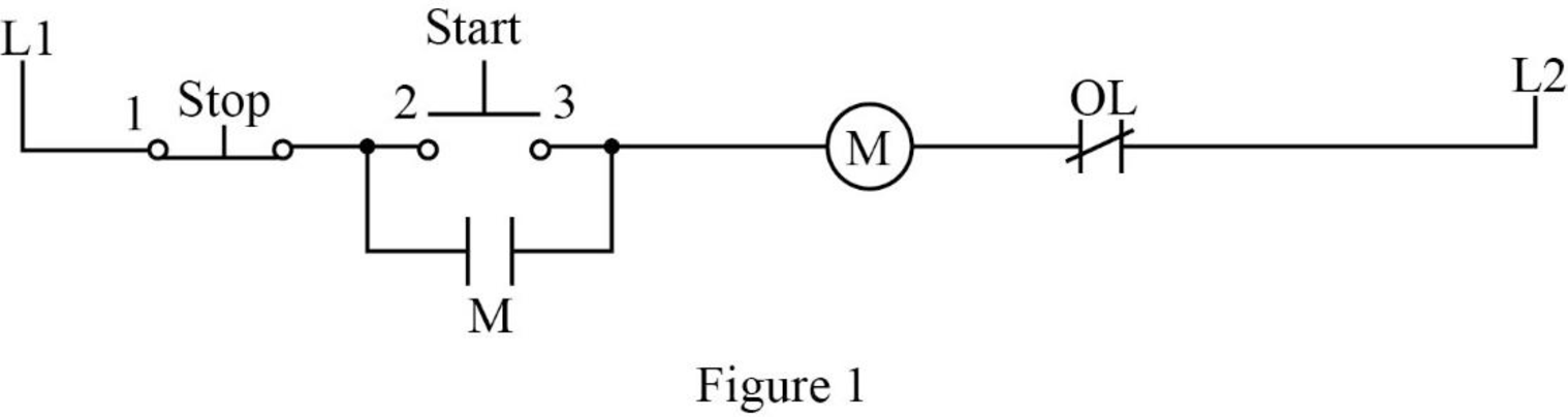
In Figure 1, when the start pushbutton is pressed, the control circuit can be completed using coil M and closes all the M contacts. It leads to close the motor connection to the line by contacting the power circuits to the motor. The auxiliary contact M, which is connected in parallel with the start pushbutton, is also closed. This M contact is used to maintain the circuit to coil M when the start pushbutton is released. Such a contact is called as holding or sealing or maintaining contact.
When the stop pushbutton is pressed, the circuit brakes and opens the contact M. After releasing the stop pushbutton, the circuit remains the same because the start pushbutton and holding contact is in the open state. In order to complete the circuit, the start pushbutton should be pressed again.
If the supply voltage of the circuit fails, it could lead to de-energize the circuit. When the power or supply voltage is restored, the circuit remains in the open state until the start pushbutton is pressed manually. Therefore, this arrangement is called as no-voltage protection and such an arrangement is used to protect both the operator and the equipment.
Conclusion:
Thus, the control circuit with no-voltage protection is drawn and the working process is explained.
Want to see more full solutions like this?
Chapter 18 Solutions
Electric Motor Control


- Find Voarrow_forward3. Use MATLAB to generate the Nyquist plot for the following system. Then, apply the Nyquist stability criterion to determine the range of K values that ensure the stability of the closed-loop system. R(s)+ K C(s) (s+2) 1 (s + 4)(s+6)arrow_forward4. Please find the stability margins from the following Bode diagrams. Bode Diagram Phase (deg) Magnitude (dB) 50 -100 -90 -135 -180 -270 10" 10° Frequency (rad/sec) 10'arrow_forward
- Using Properties to find the Z-Transform including the region of convergence for Sol x(n): = n n cos(0.2(n-2))u(n - 1) Xch]=h+1-1 (1) h+h cos(0.27 (^_1_-1)) * shift → ht 44h-13 can you complete my solutionarrow_forwardFind Ixarrow_forwardJ. na ul-n-1) X (n) = na^ = na^ u(-(n+1)) (1-1+4)= 741-1 4[cn+1)] +1 * Z (^- 1-1 (n-1) a て why ✓ (n) Z , ༥(-༡) ur-n) Znxcm) -Zx X (n) (n-1) a auc-n) = X(n) ぞ 2-9³arrow_forward

 Delmar's Standard Textbook Of ElectricityElectrical EngineeringISBN:9781337900348Author:Stephen L. HermanPublisher:Cengage Learning
 Electricity for Refrigeration, Heating, and Air C...Mechanical EngineeringISBN:9781337399128Author:Russell E. SmithPublisher:Cengage Learning