
Concept explainers
Videos
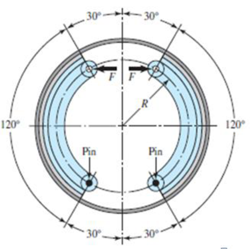
The figure shows an internal rim-type brake having an inside rim diameter of 300 mm and a dimension R = 125 mm. The shoes have a face width of 40 mm and are both actuated by a force of 2.2 kN. The drum rotates clockwise. The mean coefficient of friction is 0.28.
- (a) Find the maximum pressure and indicate the shoe on which it occurs.
- (b) Estimate the braking torque effected by each shoe, and find the total braking torque.
- (c) Estimate the resulting hinge-pin reactions.
Problem 16-1
(a)
The maximum pressure.
The shoe on which maximum pressure occurs.
Answer to Problem 1P
The maximum pressure is
The shoe on which maximum pressure occurs is right side.
Explanation of Solution
Write the expression for moment of frictional forces.
Here, coefficient of friction is
Write the expression for moment of normal forces.
Here, moment of normal forces is
Write the expression for actuating force.
Here, actuating force is
Write the expression for actuating force in reversed rotation.
Conclusion:
Substitute
Substitute
Substitute
Substitute
Since the maximum pressure occur on the right side of the shoe. So the maximum pressure occurs on the right shoe.
Thus, the maximum pressure is
(b)
The braking torque effected by right shoe.
The braking torque effected by left shoe.
The total braking torque.
Answer to Problem 1P
The braking torque effected by right shoe is
The braking torque effected by left shoe is
The total braking torque is
Explanation of Solution
Write the expression for torque applied by the right hand shoe.
Here, braking torque on right hand side shoe is
Write the expression\n for braking torque on left hand side shoe.
Here, braking torque on left hand side shoe is
Write the expression for total braking torque.
Here, total braking torque is
Conclusion:
Substitute
Thus, braking torque on right hand side shoe is
Substitute
Thus, braking torque on left hand side shoe is
Substitute
Thus, the total torque is
(c)
The resulting hinge pin reaction at right hand shoe.
The resulting hinge pin reaction at left hand shoe.
Answer to Problem 1P
The resulting hinge pin reaction at right hand shoe is
The resulting hinge pin reaction at left hand shoe is
Explanation of Solution
Write the expression for force in horizontal direction for right hand shoe.
Here, horizontal force is
Write the expression for vertical direction force on right hand side shoe.
Here, vertical direction force is
Write the expression for horizontal reaction for right hand side shoe.
Here, reaction in horizontal direction is
Write the expression for reaction in vertical direction for right hand side shoe.
Here, reaction in vertical direction for left hand shoe is
Write the expression for resultant reaction.
Write the expression for force in horizontal direction for left hand shoe.
Here, horizontal force is
Write the expression for vertical direction force on left hand side shoe.
Here, vertical direction force is
Write the expression for horizontal reaction for left hand side shoe.
Here, reaction in horizontal direction is
Write the expression for reaction in vertical direction for left hand side shoe.
Here, reaction in vertical direction for right hand shoe is
Conclusion:
Substitute
Substitute
Substitute
Substitute
Substitute
The resulting hinge pin reaction at right hand shoe is
Substitute
Substitute
Substitute
Substitute
Substitute
Thus the resultant reaction on left hand side shoe is
Want to see more full solutions like this?
Chapter 16 Solutions
Shigley's Mechanical Engineering Design (McGraw-Hill Series in Mechanical Engineering)


- Derive the equation below ah ap ax 12μ ax, +( ah ap ay 12μ ay Where P P (x, y) is the oil film pressure. 1..ah 2 axarrow_forwardCan you determine the eignevalues by hand?arrow_forwardMonthly exam 13 2021-2022 Power plant Time: 1.5 Hrs Q1. A The gas-turbine cycle shown in Fig. is used as an automotive engine. In the first turbine, the gas expands to pressure Ps, just low enough for this turbine to drive the compressor. The gas is then expanded through the second turbine connected to the drive wheels. The data for the engine are shown in the figure, and assume that all processes are ideal. Determine the intermediate pressure Ps, the net specific work output of the engine, and the mass flow rate through the engine. Find also the air temperature entering the burner T3 and the thermal efficiency of the engine. Exhaust Air intake Φ www Regenerator www Bumer Compressor Turbine Power turbine et 150 kW Wompressor P₁ = 100 kPa T₁ = 300 K PP₁ =60 P-100 kPa T₁ = 1600 K Q2. On the basis of a cold air-standard analysis, show that the thermal efficiency of an ideal regenerative gas turbine can be expressed as 77 = 1- where - () () гp is the compressor pressure ratio, and T₁ and…arrow_forward
- I need to find m in R = mD from the image given. Do you really need to know what R and D is to find R. I was thinking geometrically we can find a relationship between R and D. D = R*cos(30). Then R = mD becomes m = R/D = 1/cos(30) = 1.1547. Is that correct?arrow_forwardQ1] B/ (16 Marks) To produce a lightweight epoxy part to provide thermal insulation. The available material are hollow glass beads for which the outside diameter is 1.6 mm and the wall thickness is 0.04 mm. Determine the weight and number of beads that must be added to the epoxy to produce a 0.5 kg of composite with a density of 0.65 g/cm³. The density of the glass is 2.5 g/cm³ and that of the epoxy is 1.25 g/cm³.arrow_forwardBelow is a projection of the inertia ellipsoid in the b1-b2 plane (b1 and b2 are unit vectors). All points on the ellipsoid surface represent moments of inertia in various directions. The distance R is related to the distance D such that R = md. Determine m.arrow_forward
- Below is a projection of the inertia ellipsoid in the b1-b2 plane (b1 and b2 are unit vectors). All points on the ellipsoid surface represent moments of inertia in various directions. Determine I_aa ( moment of inertia) for direction n_a (this is a unit vector).arrow_forwardThe problems are generally based on the following model: A particular spacecraft can be represented as a single axisymmetric rigid body B. Let n₂ be inertially fixed unit vectors; then, 6, are parallel to central, principal axes. To make the mathematics simpler, introduce a frame C where n₂ = ĉ₁ = b; initially. 6₁ Assume a mass distribution such that J =₁₁• B* •b₁ = 450 kg - m² I = b² •Ï¾˜ • b₂ = b¸ •Ï¾* •b¸ = 200 kg - m² K J-I C³ =r₁₁ = r₁₁arrow_forwardThe problems are generally based on the following model: A particular spacecraft can be represented as a single axisymmetric rigid body B. Let n₂ be inertially fixed unit vectors; then, 6, are parallel to central, principal axes. To make the mathematics simpler, introduce a frame C where n₂ = ĉ₁ = b; initially. 6₁ Assume a mass distribution such that J =₁₁• B* •b₁ = 450 kg - m² I = b² •Ï¾˜ • b₂ = b¸ •Ï¾* •b¸ = 200 kg - m² K J-I C³ =r₁₁ = r₁₁arrow_forward
- The problems are generally based on the following model: A particular spacecraft can be represented as a single axisymmetric rigid body B. Let n₂ be inertially fixed unit vectors; then, 6, are parallel to central, principal axes. To make the mathematics simpler, introduce a frame C where n₂ = ĉ₁ = b; initially. 6₁ Assume a mass distribution such that J =₁₁• B* •b₁ = 450 kg - m² I = b² •Ï¾˜ • b₂ = b¸ •Ï¾* •b¸ = 200 kg - m² K J-I C³ =r₁₁ = r₁₁arrow_forward##### Determine an example of a design of a compressed air system, which uses the criterion of speed for the design of the pipes (formula attached). The demands of flow rate, power as well as air velocity in the pipelines can be freely chosen. Sizing the compressor (flow, power...) Size reservoir required Setting the dryer Determine the amount of water withdrawn from the system due to air compression **With the attached formula you can choose the appropriate values of the unknownsarrow_forwardTo make an introduction to a report of a simple design of a compressed air system, which uses the criterion of speed, and not that of pressure drop, to determine the diameter of the pipes, where the capacity of the compressor and the demands of the equipment are expressed in flow.arrow_forward
 International Edition---engineering Mechanics: St...Mechanical EngineeringISBN:9781305501607Author:Andrew Pytel And Jaan KiusalaasPublisher:CENGAGE L