
Videos
How does the voltmeter reading compare to the potential difference across the electrodes? Explain.
If the sliding lead from electrode A were connected at point C along the resistor, would the voltmeter reading be positive, negative, or zero? Explain.
(Hint: Imagine disconnecting the ammeter and evacuated tube from the rest of the circuit, and answering the same question.)
How would you adjust the sliding connection from electrode A in order to make the potential difference across the electrodes
The potential difference reading in the voltmeter.
Voltmeter reading positive, negative or zero.
To adjustment to be made for the Voltmeter reading as positive and negative.
Answer to Problem 1aT
The potential across the electrodes is equal to the potential difference reading in the voltmeter.
Voltmeter reading will be positive.
By reversing the direction of the connection of the variable battery voltmeter can read negative potential.
Explanation of Solution
Introduction:
Photoelectric effect: Electrons from a metal surface are ejected when a light of an appropriate frequency is incident on it.The ejected electrons are called photoelectrons and the whole phenomenon is called photoelectric effect. This effect was explained by The Albert Einstein.
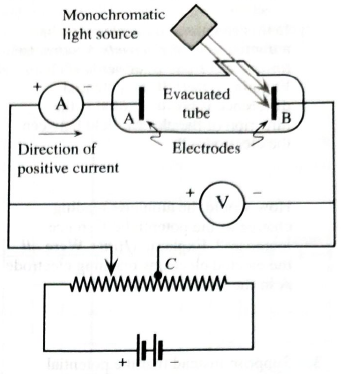
Figure 1 shows the circuit diagram to study the Photoelectric effect (PE).
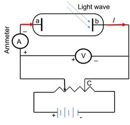
Figure 1: Set up to study photoelectric effect
A monochromatic is incident on one of the electrodes ‘b’ . Electron bonded to a metal requires a minimum energy just to leave the surface of metal is called binding energy of electron, also known as work function of the electron and denoted as
Current is flowing from positive to negative terminal of the battery (shown as red arrows in Figure 1).Therefore, the voltmeter will show the potential across electrode positive as electrons are flowing from high potential to lower potential.
Figure 2 shows the circuit diagram to study the Photoelectric effect (PE). In order to obtain the positive potentialdifference, read by voltmeter, figure 2(1) is applicable, as the electrode ‘b’ exposed to light is connected to negative terminal and other electrode ‘a’to the positive terminal of the battery. To make it more positive, one need to increase the potential of the variable battery that will make the electrode ‘a’more positive, hence will result in more positive potential across the electrodes.
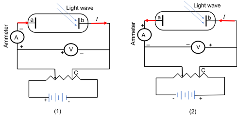
Figure 2: Set up to study photoelectric effect
In order to obtain the negative potential difference,read by voltmeter, figure 2(2) is applicable, as the electrode ‘b’ exposed to light is connected to positive terminal and other electrode ‘a’to the negative terminal of the battery.
Conclusion:
The potential across the electrodes is equal to the potential difference reading in the voltmeter.Voltmeter reading will be positive.By reversing the direction of the connection of the variable battery voltmeter can read negative potential.
Want to see more full solutions like this?
Chapter 14 Solutions
Tutorials in Introductory Physics
Additional Science Textbook Solutions
Cosmic Perspective Fundamentals
Anatomy & Physiology (6th Edition)
Chemistry: An Introduction to General, Organic, and Biological Chemistry (13th Edition)
Chemistry: Structure and Properties (2nd Edition)
Microbiology: An Introduction
Campbell Biology (11th Edition)


- Lab 8 Part 3 PHET Wave Interface simulation. I am having trouble with this part of the lab.arrow_forwardMick and Rick are twins born on Earth in the year 2175. Rick grows up to be an Earth-bound robotics technician while Mick becomes an intergalactic astronaut. Mick leaves the Earth on his first space mission in the year 2200 and travels, according to his clock, for 10 years at a speed of 0.75c. Unfortunately, at this point in his journey, the structure of his ship undergoes mechanical breakdown and the ship explodes. How old is Rick when his brother dies?arrow_forwardHi, I have canceled, why did you charge me again?arrow_forward

 Glencoe Physics: Principles and Problems, Student...PhysicsISBN:9780078807213Author:Paul W. ZitzewitzPublisher:Glencoe/McGraw-Hill
 College PhysicsPhysicsISBN:9781938168000Author:Paul Peter Urone, Roger HinrichsPublisher:OpenStax College
 University Physics Volume 1PhysicsISBN:9781938168277Author:William Moebs, Samuel J. Ling, Jeff SannyPublisher:OpenStax - Rice University
 Physics for Scientists and Engineers: Foundations...PhysicsISBN:9781133939146Author:Katz, Debora M.Publisher:Cengage Learning