
Thinking Like an Engineer: An Active Learning Approach (3rd Edition)
3rd Edition
ISBN: 9780133593211
Author: Elizabeth A. Stephan, David R. Bowman, William J. Park, Benjamin L. Sill, Matthew W. Ohland
Publisher: PEARSON
expand_more
expand_more
format_list_bulleted
Concept explainers
Videos
Textbook Question
Chapter 11.6, Problem 7CC
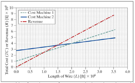 You are working for a tire manufacturer, producing wire to be used in the tire as a strengthening agent. You are considering implementing a new machining system, and you must present a breakeven analysis to your boss. You develop the graph, showing two possible machines that you can buy.
- a. Which machine has a higher fixed cost?
- b. Which machine has a lower variable cost?
- c. How much wire must be produced on Machine 1 to break even?
- d. If you make 3 million feet of wire, which machine will yield the higher profit?
- e. Which machine has the lower breakeven point?
Expert Solution & Answer
Want to see the full answer?
Check out a sample textbook solution
Students have asked these similar questions
CORRECT ANSWER ONLY WITH COMPLETE FBD. PREFERABLY HANDWRITTEN. I WILL UPVOTE
1. The beam shown carries the following loads:Total dead load, wDL = 36 kN/mConcentrated live load, PLL = 240 kNThe beam section is HSS16X12X3/8 with properties:Span, L = 6 mArea, A = 12,100 mm2Moment of inertia about x-axis, Ix = 292 x 106 mm4Fy = 345 MPa
1. Calculate the location of the live load, from the left support, for maximum moment to occur at the fixed support.Answer: 2.536 m2. Calculate the maximum moment. Answer: 439.128 kN-m
CORRECT ANSWER AND COMPLETE FBD ONLY. I PREFER HANDWRITTEN BUT ITS OKAY IF NOT. I WILL UPVOTE
2. The space truss shown is supported by ball-and-socket joints at A, B and C. Factored loads P1 and P2 areacting on joints D and E, respectively, towards the negative y-direction.
1. Calculate the stress of member CE, indicate tension or compression. Answer: 23.61 MPa Tension2. Calculate the stress of member AD, indicate tension or compression. Answer: 21.01 MPa Compression3. Calculate the stress of member CD, indicate tension or compression. Answer: 11.03 MPa Tension
CORRECT ANSWER AND COMPLETE FBD ONLY. I PREFER HANDWRITTEN BUT ITS OKAY IF NOT. I WILL UPVOTE
3. The frame has pin supports at A and E, subject to a wind load. Treat joint C to be an internal hinge.
Given:Dimensions, H1 = 3.0 m; H2 = 4.5 m; L = 10.0 mWind loads, wWL (AB) = 4.8 kN/m; wWL (BC) = 3.9 kN/m; wWL (CD) = 1.5 kN/m; wWL (DE) = 1.2 kN/mMembers are made of A36 steel Wide Flange Section with the following properties:Area, A = 64000 mm2Depth, d = 762 mmFlange width, bf = 371 mmThickness of web, tw = 32 mmThickness of flange, tf = 57.9 mmMoment of inertia about x-axis, Ix = 6080 x 106 mm4The wide flange is oriented so that the bending is about the x-axis1. Calculate the stress in member AB, due to the axial load it carries, indicate if tension or compression.Answer: 0.0476 MPa Tension2. Calculate the stress in member DE, due to the axial load it carries, indicate if tension or compression.Answer: 0.2351 MPa Compression3. Calculate the maximum bending stress at B. Answer: 4.282 MPa
Chapter 11 Solutions
Thinking Like an Engineer: An Active Learning Approach (3rd Edition)
Ch. 11.2 - In the following experimental data plot, identify...Ch. 11.2 - In the following experimental data plot, identify...Ch. 11.2 - In the following theoretical data plot, identify...Ch. 11.2 - In the following theoretical data plot, identify...Ch. 11.4 - Use the graph to answer the following questions....Ch. 11.5 - Use the graph to answer the following questions....Ch. 11.6 - You are working for a tire manufacturer, producing...Ch. 11.6 - You want to install a solar panel system on your...Ch. 11 - Joules first law relates the heat generated to...Ch. 11 - Data for a wind turbine is shown below. Use the...
Ch. 11 - There is a large push in the United States to...Ch. 11 - Your team has designed three tennis ball...Ch. 11 - Plot the following pairs of functions on a single...Ch. 11 - Plot the following pairs of functions on a single...Ch. 11 - You need to create a graph showing the...Ch. 11 - The decay of a radioactive isotope can be modeled...Ch. 11 - In researching alternate energies, you find that...Ch. 11 - Prob. 10ICACh. 11 - The following graph applies to ICA 11-10 to...Ch. 11 - The following graph applies to ICA 11-10 to ICA...Ch. 11 - The following graph applies to ICA 11-10 to ICA...Ch. 11 - Use the following graph to determine which...Ch. 11 - The following graph shows the power delivered to a...Ch. 11 - The music industry in the United States has had a...Ch. 11 - You are working for a chemical manufacturer,...Ch. 11 - Use the accompanying graph to answer the following...Ch. 11 - A company designs submersible robots with a new...Ch. 11 - Your company is manufacturing a complex part from...Ch. 11 - Prob. 1RQCh. 11 - Prob. 2RQCh. 11 - Prob. 3RQCh. 11 - Prob. 4RQCh. 11 - Prob. 5RQCh. 11 - Prob. 6RQCh. 11 - 7. Eutrophication is the result of excessive...Ch. 11 - 8. In the 1950s, a team at Los Alamos National...Ch. 11 - Prob. 9RQCh. 11 - 10. One of the 22 named, derived units in the...Ch. 11 - Shown are graphs of the altitude in meters, and...Ch. 11 - Answer the following questions using the graph....Ch. 11 - Answer the following questions using the graph....Ch. 11 - In a simple electric circuit, the current (I) must...Ch. 11 - In a hard drive design, the faster the disk spins,...Ch. 11 - We have decided to become entrepreneurs by raising...Ch. 11 - As an engineer, suppose you are directed to design...Ch. 11 - We have obtained a contract to construct metal...Ch. 11 - Your company has developed a new high-mileage...Ch. 11 - One of the 14 Grand Challenges for Engineering as...Ch. 11 - You are an engineer for a plastics manufacturing...Ch. 11 - When a wine generator is installed there is a...
Additional Engineering Textbook Solutions
Find more solutions based on key concepts
What types of coolant are used in vehicles?
Automotive Technology: Principles, Diagnosis, And Service (6th Edition) (halderman Automotive Series)
Assume a telephone signal travels through a cable at two-thirds the speed of light. How long does it take the s...
Electric Circuits. (11th Edition)
How does a computers main memory differ from its auxiliary memory?
Java: An Introduction to Problem Solving and Programming (8th Edition)
The solid steel shaft AC has a diameter of 25 mm and is supported by smooth bearings at D and E. It is coupled ...
Mechanics of Materials (10th Edition)
How are relationships between tables expressed in a relational database?
Modern Database Management
Why is the study of database technology important?
Database Concepts (8th Edition)
Knowledge Booster


Learn more about
Need a deep-dive on the concept behind this application? Look no further. Learn more about this topic, mechanical-engineering and related others by exploring similar questions and additional content below.Similar questions
- 32 mm 32 mm b' c' C 32 mm 32 mm b PROBLEM 6.41 a The extruded beam shown has a uniform wall thickness of 3 mm. Knowing that the vertical shear in the beam is 9 kN, determine the shearing stress at each of the five points indicated.arrow_forwardIn a structural reliability problem, the resistance (capacity) R and load effect (demand) S random variables associated with a failure mode of the structure of interest are normally distributed and statistically independent with the following probability distribution parameters (or statistics) in consistent units: MR = 12, σR = 3 μs = 5, σs = 2 (a) Determine the exact probability of failure pF ·arrow_forwardThe resistance R and load effect S for a given failure mode are statistically independent random variables with marginal PDF's 1 fR (r) = 0≤r≤100 100' fs(s)=0.05e-0.05s (a) Determine the probability of failure by computing the probability content of the failure domain defined as {rarrow_forwardPlease solve this problem as soon as possible My ID# 016948724arrow_forwardThe gears shown in the figure have a diametral pitch of 2 teeth per inch and a 20° pressure angle. The pinion rotates at 1800 rev/min clockwise and transmits 200 hp through the idler pair to gear 5 on shaft c. What forces do gears 3 and 4 transmit to the idler shaft? TS I y 18T 32T This a 12 x 18T C 48T 5arrow_forwardQuestion 1. Draw 3 teeth for the following pinion and gear respectively. The teeth should be drawn near the pressure line so that the teeth from the pinion should mesh those of the gear. Drawing scale (1:1). Either a precise hand drawing or CAD drawing is acceptable. Draw all the trajectories of the involute lines and the circles. Specification: 18tooth pinion and 30tooth gear. Diameter pitch=P=6 teeth /inch. Pressure angle:20°, 1/P for addendum (a) and 1.25/P for dedendum (b). For fillet, c=b-a.arrow_forward5. The figure shows a gear train. There is no friction at the bearings except for the gear tooth forces. The material of the milled gears is steel having a Brinell hardness of 170. The input shaft speed (n2) is 800 rpm. The face width and the contact angle for all gears are 1 in and 20° respectively. In this gear set, the endurance limit (Se) is 15 kpsi and nd (design factor) is 2. (a) Find the revolution speed of gear 5. (b) Determine whether each gear satisfies the design factor of 2.0 for bending fatigue. (c) Determine whether each gear satisfies the design factor of 2.0 for surface fatigue (contact stress). (d) According to the computation results of the questions (b) and (c), explain the possible failure mechanisms for each gear. N4=28 800rpm N₁=43 N5=34 N₂=14 P(diameteral pitch)=8 for all gears Coupled to 2.5hp motorarrow_forward1. The rotating steel shaft is simply supported by bearings at points of B and C, and is driven by a spur gear at D, which has a 6-in pitch diameter. The force F from the drive gear acts at a pressure angle of 20°. The shaft transmits a torque to point A of TA =3000 lbĘ in. The shaft is machined from steel with Sy=60kpsi and Sut=80 kpsi. (1) Draw a shear force diagram and a bending moment diagram by F. According to your analysis, where is the point of interest to evaluate the safety factor among A, B, C, and D? Describe the reason. (Hint: To find F, the torque Tд is generated by the tangential force of F (i.e. Ftangential-Fcos20°) When n=2.5, K=1.8, and K₁ =1.3, determine the diameter of the shaft based on (2) static analysis using DE theory (note that fatigue stress concentration factors need to be used for this question because the loading condition is fatigue) and (3) a fatigue analysis using modified Goodman. Note) A standard diameter is not required for the questions. 10 in Darrow_forward3 N2=28 P(diametral pitch)=8 for all gears Coupled to 25 hp motor N3=34 Full depth spur gears with pressure angle=20° N₂=2000 rpm (1) Compute the circular pitch, the center-to-center distance, and base circle radii. (2) Draw the free body diagram of gear 3 and show all the forces and the torque. (3) In mounting gears, the center-to-center distance was reduced by 0.1 inch. Calculate the new values of center-to-center distance, pressure angle, base circle radii, and pitch circle diameters. (4)What is the new tangential and radial forces for gear 3? (5) Under the new center to center distance, is the contact ratio (mc) increasing or decreasing?arrow_forward2. A flat belt drive consists of two 4-ft diameter cast-iron pulleys spaced 16 ft apart. A power of 60 hp is transmitted by a pulley whose speed is 380 rev/min. Use a service factor (Ks) pf 1.1 and a design factor 1.0. The width of the polyamide A-3 belt is 6 in. Use CD=1. Answer the following questions. (1) What is the total length of the belt according to the given geometry? (2) Find the centrifugal force (Fc) applied to the belt. (3) What is the transmitted torque through the pulley system given 60hp? (4) Using the allowable tension, find the force (F₁) on the tight side. What is the tension at the loose side (F2) and the initial tension (F.)? (5) Using the forces, estimate the developed friction coefficient (f) (6) Based on the forces and the given rotational speed, rate the pulley set. In other words, what is the horse power that can be transmitted by the pulley system? (7) To reduce the applied tension on the tight side, the friction coefficient is increased to 0.75. Find out the…arrow_forwardThe tooth numbers for the gear train illustrated are N₂ = 24, N3 = 18, №4 = 30, №6 = 36, and N₁ = 54. Gear 7 is fixed. If shaft b is turned through 5 revolutions, how many turns will shaft a make? a 5 [6] barrow_forwardCE-112 please solve this problem step by step and give me the correct answerarrow_forwardarrow_back_iosSEE MORE QUESTIONSarrow_forward_ios
Recommended textbooks for you
 Precision Machining Technology (MindTap Course Li...Mechanical EngineeringISBN:9781285444543Author:Peter J. Hoffman, Eric S. Hopewell, Brian JanesPublisher:Cengage Learning
 Welding: Principles and Applications (MindTap Cou...Mechanical EngineeringISBN:9781305494695Author:Larry JeffusPublisher:Cengage Learning
 Refrigeration and Air Conditioning Technology (Mi...Mechanical EngineeringISBN:9781305578296Author:John Tomczyk, Eugene Silberstein, Bill Whitman, Bill JohnsonPublisher:Cengage Learning
 Automotive Technology: A Systems Approach (MindTa...Mechanical EngineeringISBN:9781133612315Author:Jack Erjavec, Rob ThompsonPublisher:Cengage Learning
 Principles of Heat Transfer (Activate Learning wi...Mechanical EngineeringISBN:9781305387102Author:Kreith, Frank; Manglik, Raj M.Publisher:Cengage Learning
Precision Machining Technology (MindTap Course Li...
Mechanical Engineering
ISBN:9781285444543
Author:Peter J. Hoffman, Eric S. Hopewell, Brian Janes
Publisher:Cengage Learning
Welding: Principles and Applications (MindTap Cou...
Mechanical Engineering
ISBN:9781305494695
Author:Larry Jeffus
Publisher:Cengage Learning
Refrigeration and Air Conditioning Technology (Mi...
Mechanical Engineering
ISBN:9781305578296
Author:John Tomczyk, Eugene Silberstein, Bill Whitman, Bill Johnson
Publisher:Cengage Learning
Automotive Technology: A Systems Approach (MindTa...
Mechanical Engineering
ISBN:9781133612315
Author:Jack Erjavec, Rob Thompson
Publisher:Cengage Learning
Principles of Heat Transfer (Activate Learning wi...
Mechanical Engineering
ISBN:9781305387102
Author:Kreith, Frank; Manglik, Raj M.
Publisher:Cengage Learning
Dynamics - Lesson 1: Introduction and Constant Acceleration Equations; Author: Jeff Hanson;https://www.youtube.com/watch?v=7aMiZ3b0Ieg;License: Standard YouTube License, CC-BY